Hallo,
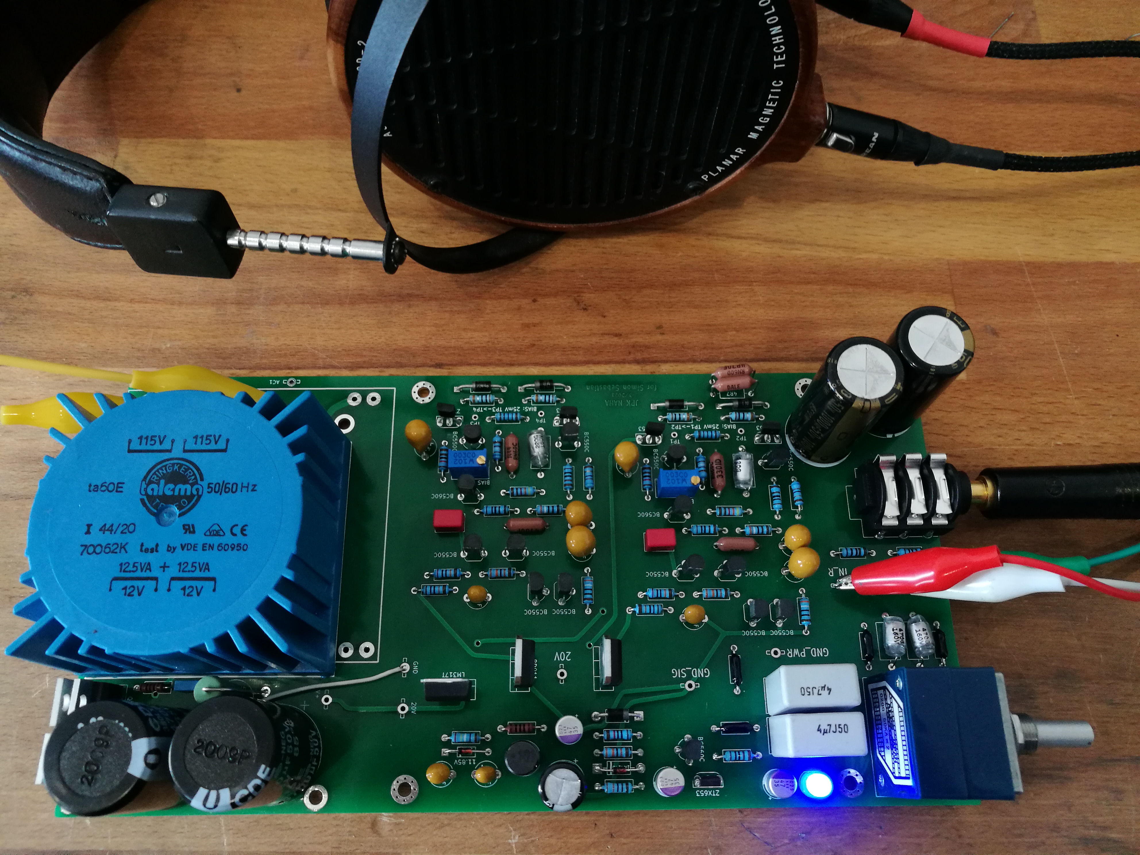
I found the schematics to the naim headline headphone amp in a polish forum. Unfortunately I don´t speak polish, so I´m bringing this over here. Also, it seems that almost anything from naim has been given the "pinkfish treatment" here, except their headphone amp.
http://img854.imageshack.us/img854/8464/21877f0c70.jpg
Guessing from the polish forum posts, I think it should be the naim headline 1, not the actual version 2 of the amp. The headline 2 is supposed to be more stable under low impedance loads.
But, after comparing component values (mostly resistors) and routing of the schematic to photos of the headline 2 and found them to be nearly identical. Also the sketched power-supply section (which I did not compare in detail) seems to fit more to the headline 2 than the headline 1. The obvious difference between version 1 and 2 are the black hats on the "input stage"-transistors, if I´m not mistaken, to keep them in thermal equilibrium.
Version 1:
http://img266.imageshack.us/img266/6791/5c38ed96f6.jpg
Version 2:
http://img545.imageshack.us/img545/8961/1000x500pxllb117364enai.jpg
Side by side:
http://img692.imageshack.us/img692/1576/nahaoliveblk2.jpg
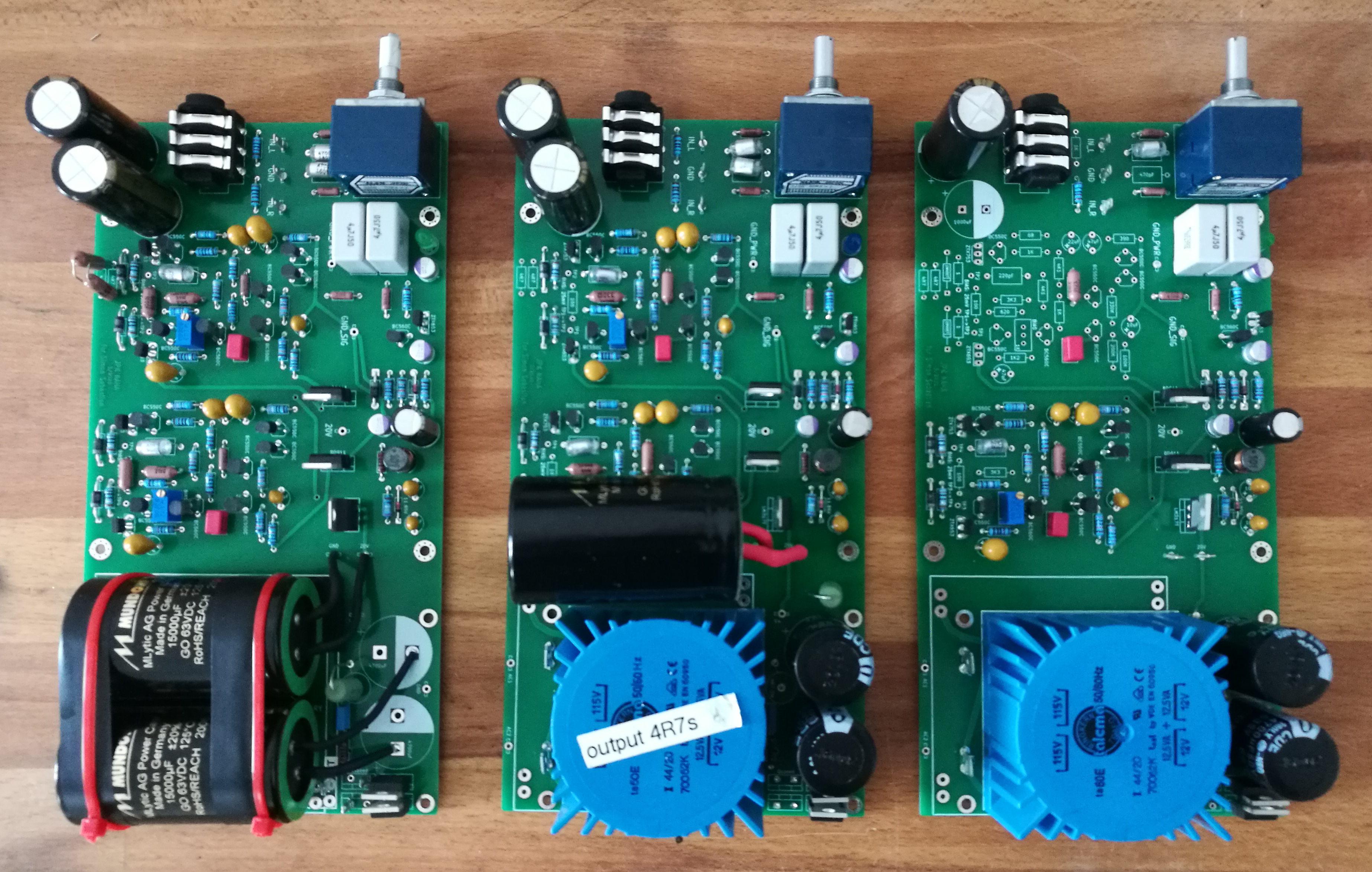
Anyway, I am in the middle of making a self-etch-pcb to the schematic and have some questions:
(1) I have 32 ohm headphones, so I would like it to be compatible, does anyone have some comments on the headline 2 or 1 low impedance load issue? I didn´t find any difference in the schematic and pictures of the HL2, the thermal coupling of the two transistors per channel seems doable, and the power supply is also not too complex.
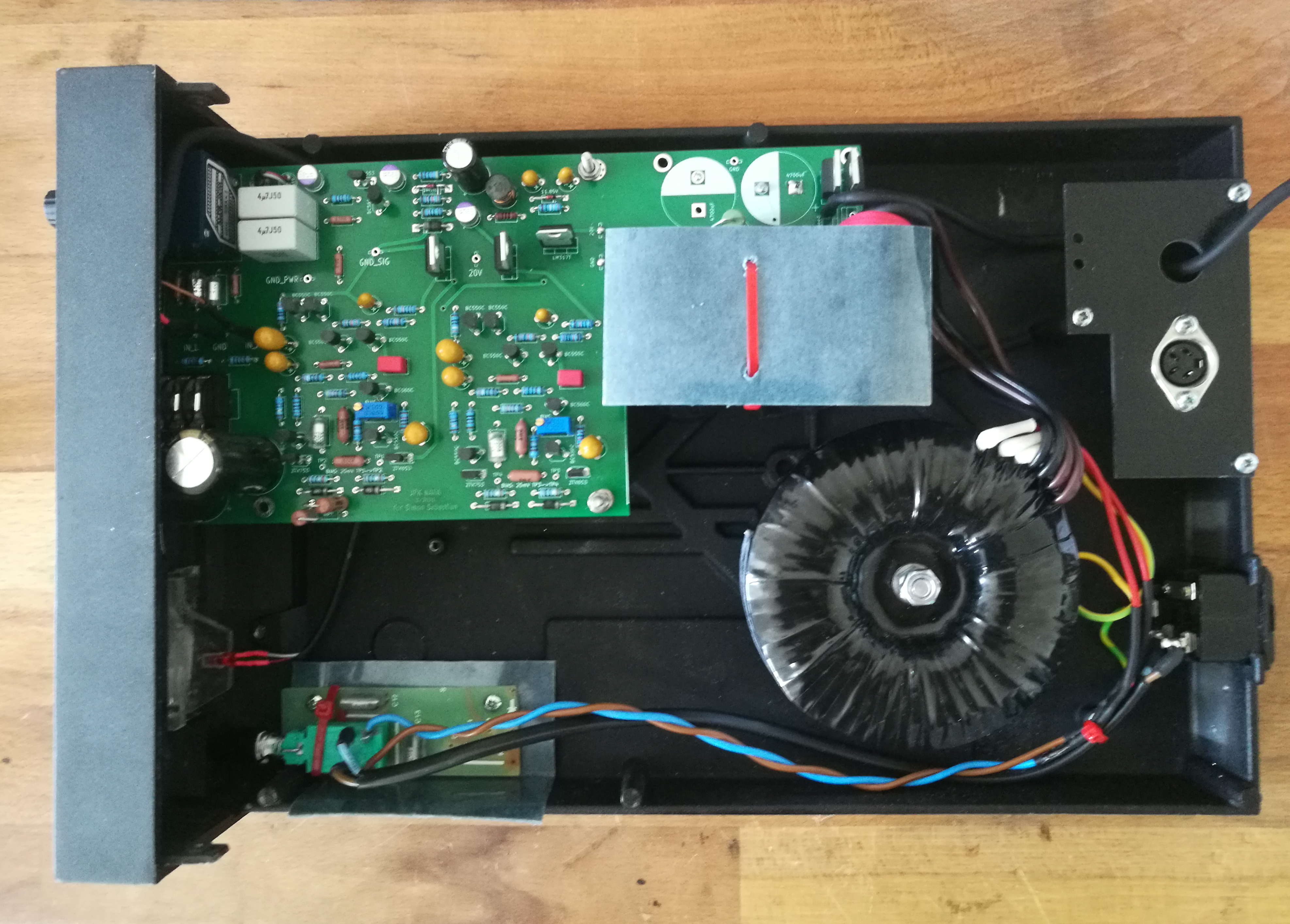
(2) Speaking of power-supply: the headline is powered by a single regulated 18-24V feed. Each channel has split local regulators (about 12-13V) for input and output stage. The output stage is supplied by a simple LM317 circuit, I guess to give low output impedance. The input stage is fed by additional regulation after the LM317. I can only speculate that this is also some variation of a gyrator, but I´m not sure. It seems more complex than a teddyreg, so I ask myself at which level this regulator type might be? Apparently it has a higher output impedance and is better suited at the input stage.
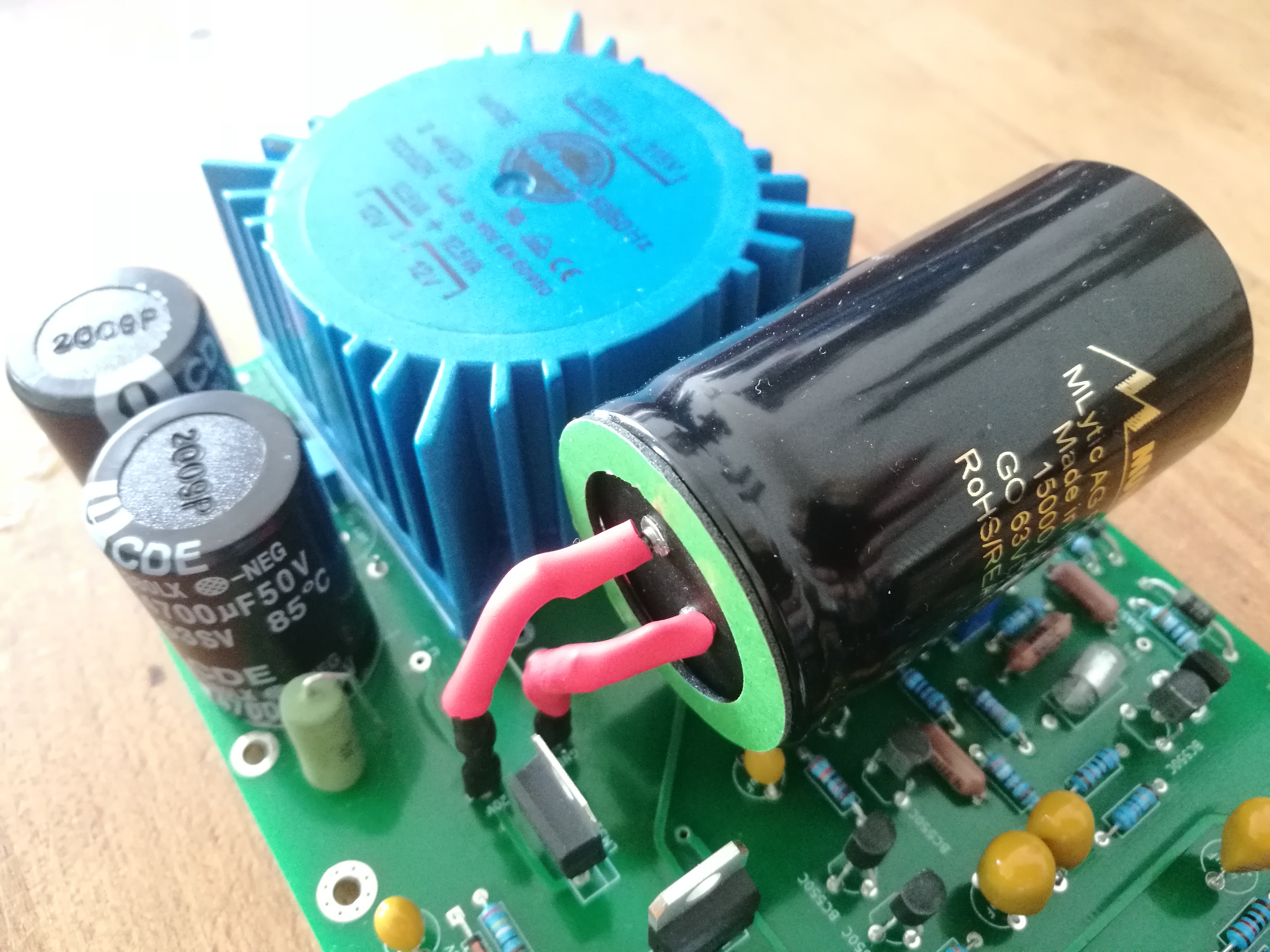
I think here can be modded the most: single transformer windings for each stage, regulators of choice. But which ones?
(3) Components: the transistors ZTX384 and 214 can apparently be substituted by BC550 and BC560 and the output transistors ZTX652 and 752 by the 653 and 753 (I found this in a thread to NAP250 transistors). Is this correct?
Is the small ceramic cap across base and collector 5.6pF like in the 321-cards? (It is "39pf?" in the schematic). Other caps are tantalum, polystyrene (470pF and 220 pF) and the big output elkos (1000uF). I guess the cap across the "central transistor" is 180 uF? (It has no units in the schematic). It seems to be on of the tantalums.
All in all, I am confident that I could knock something together, but some of the details are still not clear to me. Any help is appreciated.
Thank you
Florian
EDIT: here are some higher resolution pics and schematic:
https://www.dropbox.com/sh/w25y4ztaof6exf9/VvrZf_qm_A
I found the schematics to the naim headline headphone amp in a polish forum. Unfortunately I don´t speak polish, so I´m bringing this over here. Also, it seems that almost anything from naim has been given the "pinkfish treatment" here, except their headphone amp.
http://img854.imageshack.us/img854/8464/21877f0c70.jpg
Guessing from the polish forum posts, I think it should be the naim headline 1, not the actual version 2 of the amp. The headline 2 is supposed to be more stable under low impedance loads.
But, after comparing component values (mostly resistors) and routing of the schematic to photos of the headline 2 and found them to be nearly identical. Also the sketched power-supply section (which I did not compare in detail) seems to fit more to the headline 2 than the headline 1. The obvious difference between version 1 and 2 are the black hats on the "input stage"-transistors, if I´m not mistaken, to keep them in thermal equilibrium.
Version 1:
http://img266.imageshack.us/img266/6791/5c38ed96f6.jpg
Version 2:
http://img545.imageshack.us/img545/8961/1000x500pxllb117364enai.jpg
Side by side:
http://img692.imageshack.us/img692/1576/nahaoliveblk2.jpg
Anyway, I am in the middle of making a self-etch-pcb to the schematic and have some questions:
(1) I have 32 ohm headphones, so I would like it to be compatible, does anyone have some comments on the headline 2 or 1 low impedance load issue? I didn´t find any difference in the schematic and pictures of the HL2, the thermal coupling of the two transistors per channel seems doable, and the power supply is also not too complex.
(2) Speaking of power-supply: the headline is powered by a single regulated 18-24V feed. Each channel has split local regulators (about 12-13V) for input and output stage. The output stage is supplied by a simple LM317 circuit, I guess to give low output impedance. The input stage is fed by additional regulation after the LM317. I can only speculate that this is also some variation of a gyrator, but I´m not sure. It seems more complex than a teddyreg, so I ask myself at which level this regulator type might be? Apparently it has a higher output impedance and is better suited at the input stage.
I think here can be modded the most: single transformer windings for each stage, regulators of choice. But which ones?
(3) Components: the transistors ZTX384 and 214 can apparently be substituted by BC550 and BC560 and the output transistors ZTX652 and 752 by the 653 and 753 (I found this in a thread to NAP250 transistors). Is this correct?
Is the small ceramic cap across base and collector 5.6pF like in the 321-cards? (It is "39pf?" in the schematic). Other caps are tantalum, polystyrene (470pF and 220 pF) and the big output elkos (1000uF). I guess the cap across the "central transistor" is 180 uF? (It has no units in the schematic). It seems to be on of the tantalums.
All in all, I am confident that I could knock something together, but some of the details are still not clear to me. Any help is appreciated.
Thank you
Florian
EDIT: here are some higher resolution pics and schematic:
https://www.dropbox.com/sh/w25y4ztaof6exf9/VvrZf_qm_A