advertisement


Gyrator + tracking pre-reg (does/will it work?)

13mh13

Pi-s Artist
Pretty sure these builds were "inspired" by PFM posts and threads dealing with super regs (Teddy Pardo) and tracking pre-regs.
I built them -- one a pos reg based on lm1086s and the other a neg reg based on lm337s -- maybe 2008???
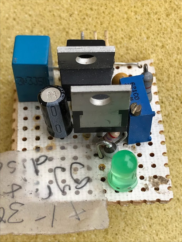
I don't recall why I never used them -- maybe they are not built correctly. One reason for incorrect built is that the variable R pot (blue) does not have any effect on output.
The pos device uses a BD139, two (tracking ??) lm1086s, and various passives.
If I connect the three terminals to respective Out, In, and GND, I will get a very clean V_out (not loaded) with no more than 1.5v drop. Clean from 3-30 vdc, with no more than 1.5mV AC ripple.
So does that voltage make sense?


No schematic.
Pardo did create a lot of confusing threads here on PFM. I think part of my two devices were based on:
But I could not find a schema in that thread. Maybe one you readers could help.
Clark's projects on acoustica are nice and detailed. Built several of those TPRs, that are still in daily use, and 15 years reliability!
With those weird mysterious projects that I built could could not figure out, I simply deconstructed one of them (+, LT1086); and with the parts just built the datasheet ckt. This gave me perhaps the lowest ripple I have ever seen in any reg. I have built (less that 1.0 mv when the reg settles down after 30 sec).
Those LT and Fairchild engineers spent a lot of time, effort and resources into the OEM design. Maybe the best option has been in plain sight all this time. So all the myriad thread DIY projects are ... ahem ... delusions.
 
It can be made to work, sure - but is it efficient and effective for the cost...?* and note, exactly how you connect-up such a thing can make or destroy ..a couple of aspects of performance.

* I suggest no - there are simpler, cheaper, easier to implement well, more reliable things , like C-R-C or C-L-C on the raw input.
Either of these can easily drive-down incoming noise to the point that the 3-pin regs are the limit, for pennies; and with no stability issues.

(sorry - short on time: little diagrams & value suggestions to follow soon, and measurements from another)
 
(sorry - short on time: little diagrams & value suggestions to follow soon, and measurements from another)
While you've got a pen out, draw up the schematic for Pardo's
All he did was show some pretty pictures. And that thread ran 10 pages w/o a schematic. Weird!


BTW, I've always been clear that IMO - the 'teddyreg' approaches utterly throw the baby out with the bathwater. 'low noise' seen from what is incoming sure - but the resulting output AC impedance is so high, that it does not control the load side.

This is a big deal for the reasons you want 'good regulation' (which is a 'low AC-impedance, over a wideband' property.)
Yes- you read that right: what sets 'good' DC voltage regulators apart - is their AC performance, wideband.


; )
I thought you were going to stick with the subject of this thread, guv, and draw up a schema of the gyrator?
What Pardo came up with in 2006 (see link in my prev. posts). I think you, guv, noted something like using a bd139 instead of Pardo's orig bc547.
 
We do not know the circuit in question, so any response is speculative.

A gyrator / capacitor multiplier, before a 3-pin regulator, is commonly used to increase the input noise rejection. A tracking pre-regulator does the same job as the gyrator. 3-pin regulators are noisy though. The original Witch Hat Newt used a tracking pre-regulator, which was quieter than a 3-pin alone, but not by much. That led to the Witch Hat Dragon Newt, a discrete regulator, which is very quiet indeed. Alternatively, I believe Avondale's solution uses current dumping, but that might burn energy. Another is the ALWSR. Naim has its own discrete regulator of course, but I don’t know how any of these compares in terms of noise. More modern (monolithic) regulators are supposed to be quieter too e.g. the AMB sigma 78.

All of the above have a low output impedance. The problem here is that the required feedback mechanism reacts to any capacitance at its output, causing oscillation. You mention Teddy Pardo, which probably put a bee in Martin Clark’s bonnet. Staying off topic, one of TP’s solutions (probably not this one) was to remove that feedback mechanism, meaning the output impedance was a few ohms, but now we’re immune to oscillation. Plus there’s little noise injected back into the input, meaning that many regulators can share the same supply. To a degree, a gyrator may do that too. I don’t believe that any regulator rejects all of the noise from its input though, hence Martin’s suggestion of CRC supplies.

Continuing off topic …

Don’t forget though that the Naim circuits had a 27ohm resistor in series with the DC supply, which is much higher than the Teddy Reg output of a few ohms at DC. Without that resistor, then the improvement with a (local) TR, due to reduced noise, is very audible. A capacitor following the supply will keep the AC impedance low.

There’s no right or wrong answer; it depends upon the application. Discrete regulators are much larger than TRs, meaning they may have to be mounted in an external case, leading to more problems in terms of feedback (oscillation). Would that there were, but there’s no catch-all solution and it requires careful evaluation.
 
Last edited:
The sketch I mean to do , is simple C-R-C, or C-L-C before a regulator (or tracking pre-reg), with value suggestions.
There's a point , very quickly approached, where there's no point going further - because the self-noise of the regulator(s) dominate.


@Avon 's post above is spot -on (except I've no bee in my bonnet about TP approach at all; there are a few instances where it's a good starting point; such as say phono stages - low noise, low-but-constant current draw, so definitely worth considering ; ) )
 
The sketch I mean to do...
Back of the envelope ... use a pen and junk mail paper. Take a photo with your phone. Easy peasy, guv.

Start with this first (unless you don't really think it is all that special of a "design") ...
IMG_7359.jpg
 
Wtaf are any of your pics supposed to show?
You want more input, you are going to have to provide plenty more yourself for once.

Draw out the network for each of the above, with parts values; declare what you are trying to achieve, rather than leach.
 
Oops ... forgot this one from my parts bin ... a (pos) unit based on dual (tracking) lm317s. Built (and behaving) exactly like the other two prev. mentioned: excellent performance but useless var. pot (the blue device). R4 (1k Bourns) from:
That's what I need to work, so I can adj. to +5v.

I'm now guessing they were all built "correctly" in their 2008 build: output is a VERY clean voltage of about 2.5v below input. From 3v to 30v.

Maybe the bd139 in the ckt is gettin' in the way of adjust-ability?

Photos below ... plus bonus FREE shots of the mystery project for which the titular device(s) may be incorporated into ...


Last edited:
Right - noted.

I'll have time to scribble something tomorrow; there's a very simple but high-performing way of getting as quiet as possible 5.0-5.1vDC with a 3x7, with or with tracking pre-reg - and no adjustment pot.

You are going to need three of those basic green LEDs (that measure about 1.9 - 1.95 v with 5-10mA running through them) for each new 5v reg.
 
You are going to need three of those basic green LEDs (that measure about 1.9 - 1.95 v with 5-10mA running through them) for each new 5v reg.
The LED is just an idiot light; I put LEDs into all my regs just as an ON/OFF indicator . And LEDs and their current limiting R will gently drain caps at power down.
 
As I've noted here at PFM several times, I have built many of the TPRs (Acoustica page 4) ... and some of the images of same PS box, part of my Magnavox Mess project, are shown below. Some TPRs are in other devices so I probably have about dozen around, some in daily use.
In these photos, some TPRs are +5v (based on two LM317), some are +15v, etc.
The TPRs are further, modified per my own experiments, with snubbers and de-noising Rs.
Anyway, the main point is that all of these TPRs in photos below behave like they should. I can tweak V_out using the R4 Bourns trimpot.

But something not quite right with that "gyrator" in top post: The R4 trimmer is useless.


Last edited:
But something not quite right with that "gyrator" in top post: The R4 trimmer is useless.
The trimmer will set the output impedance of the gyrator. If that base resistor is set to 2k, you'll get maybe 10R feeding the regulator. It's a matter of adjusting that for best performance. Martin Clark once recommended not going more than about 10R to feed a regulator, for stability reasons.
 
Gyrator and tracking preregulator with an improved voltage reference was how my original Newt regulators were done. They were a great improvement over the standard LM317 implementation.


advertisement


Back
Top