
teddy_pardo
Trade: Teddy Pardo
Here is an attempt to summarize the original long (and maybe confusing) TeddyReg thread. My preferred implementation is with a Fetlington (thanks to pigletsdad for the idea, and to agent_cooper79 for taking the initiative and providing the transistors).
I'll start with the diagram for the positive circuit:
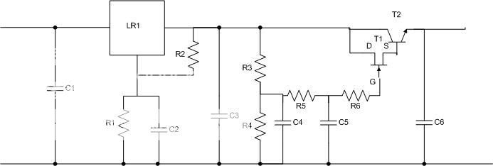
Resistors R1 and R2 are used to set the voltage at the output of the linear regulator LR1.
The output is
Vlr1 = 1.25 x (1 + R1/R2)
R2 is anything between 100R and 1000R
The dropout on the gyrator is determined by the ratio of R3 and R4 plus the dropout on T1 and T2. The resistor dropout is a percentage of Vlr1 and is equal to Vlr1 x R3 / (R3+R4). The dropout on T1 and T2 is constant and equal to around 1V on load.
The list of components for a positive 25V regulator is:
R1 = 3.4K
R2 = 150R
R3 = 150K
R4 = 1M
R5 = 100K
R6 = 100-250R
C1 = 0.1uF X7R Ceramic
C2 = 10-20uF Tantalum
C3 = 10-20uF Tantalum
C4 = 20-33uF Tantalum
C5 = 0.1-0.3uF X7R Ceramic
C6 = 10-20uF Tantalum/Oscon or 100uF Silmic, or even better 1-10uF film capacitor (MMK/MKS)
T1 = 2SK117 - GR
T2 = D44H11
LR1 = LM317/LT1086
For the negative version
T1 = 2N5460 (note that the pin layout is different)
T2 = D45H11
LR1 = LM337 (note that the pin layout is different)
Obviously the capacitor polarity should be inverted.
I would recommend to divide the dropout between LR1 and the gyrator evenly. As an example, if the input voltage is 33V and you want the output to be 25V, set LR1 to 29V.
Notes:
1. The no-load voltage is around 0.5-1V higher than the on-load voltage. It is due to the fact that when no current passes through the transistors there is no dropout on them. It can be avoided by adding a 1K - 3K resistor at the output of the regulator, but it's usually not needed.
2. With high values of R3 (50K and above), it takes several seconds until the output voltage rise to the desired value. If you need faster settling use smaller resistors, but the results will not be as good.
3. If you don't want to bother with FETs which are sometimes hard to find, low noise bipolar transistors BC550C/BC560C provide very good results as well.
4. C1 is optional and required only if the regulator is far from the power supply.
Here are some pictures of a positive and negative regulators, mounted on a strip board. The board needs to be cut in one single place only, below the FET.


Hope that helps.
Enjoy, Teddy
I'll start with the diagram for the positive circuit:
Resistors R1 and R2 are used to set the voltage at the output of the linear regulator LR1.
The output is
Vlr1 = 1.25 x (1 + R1/R2)
R2 is anything between 100R and 1000R
The dropout on the gyrator is determined by the ratio of R3 and R4 plus the dropout on T1 and T2. The resistor dropout is a percentage of Vlr1 and is equal to Vlr1 x R3 / (R3+R4). The dropout on T1 and T2 is constant and equal to around 1V on load.
The list of components for a positive 25V regulator is:
R1 = 3.4K
R2 = 150R
R3 = 150K
R4 = 1M
R5 = 100K
R6 = 100-250R
C1 = 0.1uF X7R Ceramic
C2 = 10-20uF Tantalum
C3 = 10-20uF Tantalum
C4 = 20-33uF Tantalum
C5 = 0.1-0.3uF X7R Ceramic
C6 = 10-20uF Tantalum/Oscon or 100uF Silmic, or even better 1-10uF film capacitor (MMK/MKS)
T1 = 2SK117 - GR
T2 = D44H11
LR1 = LM317/LT1086
For the negative version
T1 = 2N5460 (note that the pin layout is different)
T2 = D45H11
LR1 = LM337 (note that the pin layout is different)
Obviously the capacitor polarity should be inverted.
I would recommend to divide the dropout between LR1 and the gyrator evenly. As an example, if the input voltage is 33V and you want the output to be 25V, set LR1 to 29V.
Notes:
1. The no-load voltage is around 0.5-1V higher than the on-load voltage. It is due to the fact that when no current passes through the transistors there is no dropout on them. It can be avoided by adding a 1K - 3K resistor at the output of the regulator, but it's usually not needed.
2. With high values of R3 (50K and above), it takes several seconds until the output voltage rise to the desired value. If you need faster settling use smaller resistors, but the results will not be as good.
3. If you don't want to bother with FETs which are sometimes hard to find, low noise bipolar transistors BC550C/BC560C provide very good results as well.
4. C1 is optional and required only if the regulator is far from the power supply.
Here are some pictures of a positive and negative regulators, mounted on a strip board. The board needs to be cut in one single place only, below the FET.
Hope that helps.
Enjoy, Teddy
")