advertisement


Got Fleas?

That's true, the 1541 needs a bitclock of 1/2 MCLCK, 5.14Mhz in other words. D-flipflop is the way to do it.

Sparts155 alludes to a very good point though - some CD implementations have key inversions or delays in the timing distribution to suit the requirements of chipsets or maybe even to deal with clock skew from driving lines across the board. I'm pretty sure the Naim implementation is 'one size fits all' across the models using a 74HC04 though - and for these the output lines are all in phase, and short.
 
martin clark said:
:)

Good-oh, a few more volts in won't harm for sure.


Just finished doing it! Swapped the Trafo and smoothing caps to give a nominal 24V, replaced the 7808 on the flea back to 7812 (still in TO-92).

Result:

WOW!!!!!!!!

The improvement was instantly noticeable. Quite amazing soundstage, detail, layering, texture, micro dynamics - just about everything was fundamentally improved. I was expecting a barely noticeable improvement but this was quite staggering.

I'm still amazed that at this level it is still possible to get a step change improvement in performance but there it is.

Well done to everyone involved with bringing us the flea.

Stu.

Footnote: In a fit of madness I just ordered a Chord DAC64 (and 2nd hand audiolab transport) that was going cheap at audio-T due to closure of one of their branches. The reasoning is that as well as CD playback it would also work well with a squeezebox etc. Now I am seriously worried (!?) that it won't be a significant improvement over the modded CD5. Let you know when it arrives...
 
Now I want to fit this divider to feed the Flea into the BCK of the TDA1541 direct, main thing I need is a nice clean little supply for the 74HC163, any recomendations guys? ideally I want something small mainly to just try this out but of course I want it to give good results too, after trying this I may try out the DEM reclocking too:D
I do have a spare flea pcb I could use to power the 74HC163 but don't want to really waste it here if possible so any idea's would be much appreciated:)
 
Can't you locate the divider near near the dac on a piece of copperclad PCB and use the 5v supply from the 7220 you removed..?

That said, I'd be very tempted to use another flea, because you don't want PSU noise feeding-through into the logic gate's uncertainty. You could of course do it at low cost - tap power off the raw supply for the 7220's local reg, and use an alternative (cheap) opamp, somethign like an NE5534 will still handily outperform any 3-pin reg.

I've got plenty of spare boards if you want another to play with.
 
Oh no, I know Ron - he's like Carl, just keeps going and going, i can see an Arcam full of Fleas in a week or so ;)

I bet he's itchin to get at it (deary me :D)
 
martin clark said:
Can't you locate the divider near near the dac on a piece of copperclad PCB and use the 5v supply from the 7220 you removed..?

That said, I'd be very tempted to use another flea, because you don't want PSU noise feeding-through into the logic gate's uncertainty. You could of course do it at low cost - tap power off the raw supply for the 7220's local reg, and use an alternative (cheap) opamp, somethign like an NE5534 will still handily outperform any 3-pin reg.

I've got plenty of spare boards if you want another to play with.

Cheers Martin,

I think using a flea to power the 74HC163 would be the best bet, if you've got any boards spare I can buy from you a bit later then that would be great:) I'll have a look to see what bits I have spare, if I've enough it would be nice to be able to get it knocked up over the weekend, I do know I have a AD797 spare, not sure about the rest of the bits yet

Suppose I could run it from the little separate transformer which is feeding the Flea XO or do you think I should try and squeeze another transformer in:eek:
 
trancera said:
Oh no, I know Ron - he's like Carl, just keeps going and going, i can see an Arcam full of Fleas in a week or so ;)

I bet he's itchin to get at it (deary me :D)

Now would I do that:D
Don't bother answering:p

I wish I could get my hands on something like a CD3, there seems to be plenty more room in those for me to go mad!
 
<tempts ron>
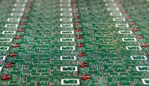
flea_pcb.jpg


No problem, plenty spare. I wouldn't worry about the second transformer, I'd be tempted to bolt two pcbs stacked together with a short standoff, tie the PSU inputs and the Ov (at the output pads) and treat as one assembly. Scraping the resist off the area marked for the XO would probably give you enough space to mount the divider chip too.
 
martin clark said:
<tempts ron>
flea_pcb.jpg


No problem, plenty spare. I wouldn't worry about the second transformer, I'd be tempted to bolt two pcbs stacked together with a short standoff, tie the PSU inputs and the Ov (at the output pads) and treat as one assembly. Scraping the resist off the area marked for the XO would probably give you enough space to mount the divider chip too.

Looks like you got a few then:eek:

Thanks again Martin, I'll have a look through my bits and pieces, hopefully I've got everything because I'm itching to get it done
I'd like to stack the flea's but they may be a bit high, theres hardly any space in this stinkin Arcam:) should be ok to try though and seeing as though the lid is hardly ever on it shouldn't cause a problem

Just wondered, has anybody used a Rubycon ZA for the 47uf? I've got a couple of 35v 10uf tants but none in 47uf, just wondered how well the ZA's work here
 
Try it and tell us!

Don't worry about the uF value, it doesn't much matter. That cap rolls-off noise gain for the amp; since it bypasses the1300ohm resistor it means the amp sees more feedback for AC than it does for DC; this promotes lower noise - and better stability. Look on it as a signal cap though...
 
martin clark said:
Try it and tell us!

Don't worry about the uF value, it doesn't much matter. That cap rolls-off noise gain for the amp; since it bypasses the1300ohm resistor it means the amp sees more feedback for AC than it does for DC; this promotes lower noise - and better stability. Look on it as a signal cap though...

Ok, will do:)
Just to prove how bad my memory is I actually etched a flea before the pcb's was ready, unfortunately I only had a 16.934 Trichord crystal so was unable to try it in anything:p I could whip the Trichord crystal out and use that to just test with the 74HC163 http://pic20.picturetrail.com/VOL1293/4634025/9699445/139431258.jpg
 
just tried the active divider, its not bad at all:) not a huge difference but noticeable.
I got the best results by running the XO out straight to the 74HC163N (no resistor ) I then swapped R214 (120ohm) on the Arcams board to 47ohms which goes to the 74HC163N output and to the BCK pin2 of the TDA1541A

I may lower R213 and R215 which go to Pin1 (WS) and Pin3 (Data) which are 390ohms, seems a bit high really

If your reading Trancera it may be worth you swapping R214 to a 47ohm or 33ohm and running the XO out directly to Z208 in your A5+, its easy enough to try and is reversable

I always wondered why pin 2 and 4 of the TDA1541A in the Arcams are joined together:confused: pin4 is supposed to be unused on the A version of the TDA1541, any idea's? maybe Arcam was ging to use the standard TDA1541 but moved to the A version
 
I may lower R213 and R215 which go to Pin1 (WS) and Pin3 (Data) which are 390ohms, seems a bit high really
Somewhere I've read info from someone at Philips which says, basically, that RC filtering the signals to the input pins is a good idea for the 1541 - ie R values c.1K are actually a good idea, even using 10-15 pF of added (external) capacitance to give a slight rolloff which keeps HF noise out of the substrate. It's tied to the way this particular dac is built and operates, and does not affect jitter etc. Also, and specifically, dropping tHe values and coupling faster signals into these inputs does not help!

So if its working OK maybe leave this bit alone. I'll have a dig later for references...
 
martin clark said:
Somewhere I've read info from someone at Philips which says, basically, that RC filtering the signals to the input pins is a good idea for the 1541 - ie R values c.1K are actually a good idea, even using 10-15 pF of added (external) capacitance to give a slight rolloff which keeps HF noise out of the substrate. It's tied to the way this particular dac is built and operates, and does not affect jitter etc. Also, and specifically, dropping tHe values and coupling faster signals into these inputs does not help!

So if its working OK maybe leave this bit alone. I'll have a dig later for references...

Thanks Martin,

I've noticed a lot of cdp's normally use only 22ohms for all the i2s lines, well the Arcams sounding ok so I'll leave them alone.
I know my diy external dac using the double crown sounds better with no resistors here but it does use an Asychronous Reclocker on the i2s so maybe its something to do with that:)
 
Hi Hacker,

The Flea is functional but not connected yet. Question is, if the clock outputs are used to clock the dac and decoder, what is likely the best output wiring configuration?. The Acoustica site says use mini coax, with the shield of one connected at only the source end to avoid ground loops, whereas the Flea manual states twisted pair. Twisted pair would be OK for one of the connections, for the second does one still use a twisted pair but with the DAC or decoder end of the ground not connected - but confused on this one, must be past bedtime!!!

Regards

Martin
 
You only want one 0v link, so use whatever's easier. That's usually three wires twisted closely together, one 0v and two signal leads carrying signal outputs. solder the 0v link close to the DAC clock input, and lead the other signal wire out to its desitination from there.

I'll take the mini-coax advice down at some point since it's very fiddly to work with, esp. in short lengths where it offers no advantage anyway!
 
Martin,

Thanks for the clarification. Now having had the CDX case open for a while the installation is getting closer. Looks like with an XPS, retaining the CDX transformer and the rectification from one of the transformer windings, it should be possible to provide an isolated 22v supply to the Flea. One CDX winding appears to supply +15v, the other + and -22.2V.

The +15 winding can be disconnected completely. This leaves the +/- 22v one. Naim appear to have done us a favour here as the 0v center tap connection appears to connect to the main part of the board via a wire! Hence, disconnecting this wire, remaking it's connection the 0v line for the Flea together with the +22v line, should give an isolated supply using the existing previously unused onboard supply in combination with an XPS.

Still a few days (weeks) away from installing but progress is being made.

Regards

Martin
 
Any more progress reports? There are fleas PCBs out there the world over, and we want to hear how things are going, whether good, bad or merely indifferent!
 
It does seem strange, theres only around half a dozen people who have posted the results, I got mine in as soon as it arrived:p

I removed the diy active divider from the TDA1541S2 in my modded Arcam and tried it so the flea just goes straight to the SAA7310 rather than both SAA7310 and dac, to be honest I think I prefer it this way
BTW powering the divider from something like a separate flea supply is deffinately a must if anybody else wanted to try it for best results

Do you think the Flea would be up to powering the SAA7310 Martin or would its current be too high?
 
I ordered the XO module few days ago, My Flea is tested and ready to accomodate it. I will report as soon as I get it.


advertisement


Back
Top