advertisement


Got Fleas?

martin clark

pinko bodger
...PFM Fleas, that is:

DSCF1881.jpg


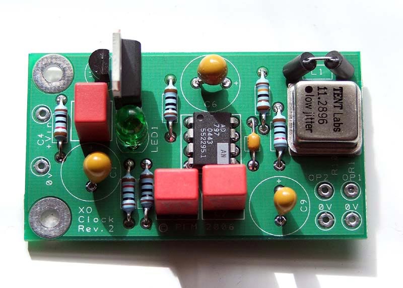
Well here's a first pass at a manual; comments and queries welcomed, and I hope it's enough for those of you who purchased kits to get started:

Build Manual(4.2MB)

Meanwhile, please use this thread to post any queries or problems arising with Flea assembly and we'll do our best to, um, debug them...
 
Shouldn't it be called the PFM Tick then?

Nice bit of work btw, very professionally turned out.

Craig
 
.Perhaps..... though it would have been better in the DIY forum! Wot an amateur; I 'll ask a kind mod to move it...
 
Great stuff Martin, and thanks for your efforts. It should take an exceptionally skilled bodger to go wrong with such thorough documentation ....

Just a note - C8 in the guide is described as 470pF, as opposed to 47pF.
 
Fantastic write up and SUPERB photos. Im very grateful.

So stupid Question 1: You say in the document that a seperate power supply is highly recommended. If this is the case I think im struggling for space a little (I see yours at the bottom of one of the final pictures). I do however have to hand some small encapsulated transformers from RS which I can fit in.

What is the min/max voltage I can use and how much current is needed.

They are 12V. So Perhaps I could get about 16V dc but that may have some serious ripple, not sure.

Anyway if not I might just have to tap off somewhere on the Arcam 5s audio board, would i be dissapointed and eternally questioning my loss!

Or I have a wall wart but its a bit high at > 24Vdc

Maybe something for that end of the manual.
 
Yes, I'll cover this in more detail following Stu's query in the 'Best clock' thread.

As set up, the Flea really needs 18v input, which is spent as follows:
1.6V drop across the cap. multiplier
2v drop-out for the 7812
12V for the 7812 output, plus 2v from the LED

-meaning that 17.6v is about the absolute minimum guaranteed the thing work as-is. If you have 16v to hand then swapping the 7812 for a 7809 is the most expedient solution, which drops the minimum input to 15V BUT this getting close to the lower limit of the AD797's qualified supply specification.

Maximum input voltage is set by the rating of cap C1, call it 30v since it's not good to run caps close to the rated voltage. Swap C1 for a 50V part if that's a problem.

The total current demand is tiny, c.20mA. Actually, the 797 draws about 8-10mA, the XO about 6-9mA (these vary by sample) and the rest is 'spent' through the LED and the feedback network (2.5mA @ 5v). Incidentally, measuring the voltage drop across the 0R5 resistor is the best check for oscillation problems too - if you start seeing 15mV or more between the 7812 output and the AD797 power supply pin (pin 7) then something's not right.
 
Thanks Martin, what is the Max voltage then, If I took the small xfr, dual secondary would be like 32V. Way too much I guess (even though the 7812 can take 35V input), perhaps not ideal for the cap multiplier ?

Guess I should have planned a little better but didnt think I'd have the time this weekend :rolleyes:
 
No that's just fine, but increase C1 to a 50v part (any old small electrolytic will do, really).

The BC547 is rated 45v minimum collector-emitter and the film caps are 50v so you'll have no problems with the cap-multiplier.
 
Nice one, Martin! I'm sure that will help everyone tremendously. In your pictures on page 4, where you show the surface mounted resistors, is the 33R the on the left? Also, there are a number of unused SMD pads on the back of the PCB, what is their purpose?

Regards,

Mus

P.S. Is it worth substituting C1, C6 and C9 for silmic IIs?
 
Mus said:
Nice one, Martin! I'm sure that will help everyone tremendously. In your pictures on page 4, where you show the surface mounted resistors, is the 33R the on the left? Also, there are a number of unused SMD pads on the back of the PCB, what is their purpose?

Regards,

Mus

I dont think there are any unused pads, I think that image should be changed, if im ok then it did confuse me.

Please tell me im ok. I have put 33 on R11 (OP1) 100 on R10 (OP2). The two 1R resistors in the centre R2 and R9 under op amp and finally surface mount caps left and right.


The first page of the manual should be "Don't start assembly after two nights out on the lash"

This is no joke - I actually thought those surface mount components were packing that had just come off from something else, till i noticed the colours carl had marked on them ?!

I hope im ok, i measure the right resistances and cant measure the resistance of the caps - which hopefully means I havent soldered all the pads together! :)
 
Mus - the empty pads should have the output resistors on them. The first photo shows the two 1R SMD mounted, the second the SMD ceramic caps, but not R10, R11. Didn't spot that until this morning... I'll update the confusing photo at some point.

C1, C6, C9 can be silmics, oscons, tants, non-name electrolytics or handmade beeswax-and-gold-foil if you like. This is an experimenter's board - and you should find that apart from the 797 and it's C8, parts are not critical to its performance. That's a good thing.

Trancera - you have it right. It really doenst matter which pad the 33R lands on, just remember that's the clock output to the DAC.
"Don't start assembly after two night out on the lash"
:D I like it, though I'm scribbling the manual in that state...
 
P6 C6 47uf 6.3V , I have a 16V ?

C8 is the small round axial cap and is non polarised ? (cant see its value, but looking at your pic)

Also a note about polarity, though should be obvious for C6,C9 and C1 might be useful to some.

Honest i didnt do it, but ohhhhh so nearly, it was in but not soldered.
 
I haven't been on the lash, but I do have a stinking cold, so bear with me. Having checked several times, I can still only see 4 surface mount devices in my pack (colour coded:2 black, 1 red, and 1 green). The first pdf picture also shows four SMDs. I take it I need some more parts then?

Regards,

Mus
 
Green for me I think was 100 , I put it in R10 for the decoder (OP2)
Red was 33, R11 for DAC (OP1)

I then had a pair packaged together with no colour these are 1 Ohm

I think the black marked were my smt Caps

If im correct and you cant find them then you dont have 1 ohms?

Check carefully, some bits stuck to the tape on my crystal
 
trancera said:
Check carefully, some bits stuck to the tape on my crystal

I found them, the little suckers had escaped from the Ziploc bag and stuck to the bubble wrap tape. Obviously, the bubble wrap was in the bottom of a bin, but luckily only the office bin. Strange that Martin's picture is missing two SMDs as well though. Thanks for the tip.

Regards,

Mus


advertisement


Back
Top