Tony L
Administrator
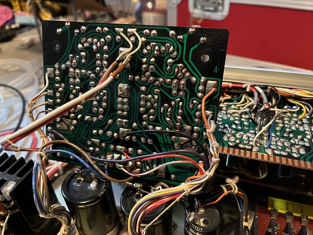
To be honest that doesn’t daunt me. The preamp is absolutely fine, so nothing to do there for now, and I’ve already reflowed the majority of this board. This sort of work doesn’t phase me, I’ve got good tools and decent skill. I hit a brick wall fast and hard with knowledge. To my eyes the soldering looks fine, though most of the transistors have tarnished legs, so any of them could be problematic in this regard even if the joint superficially looks good.
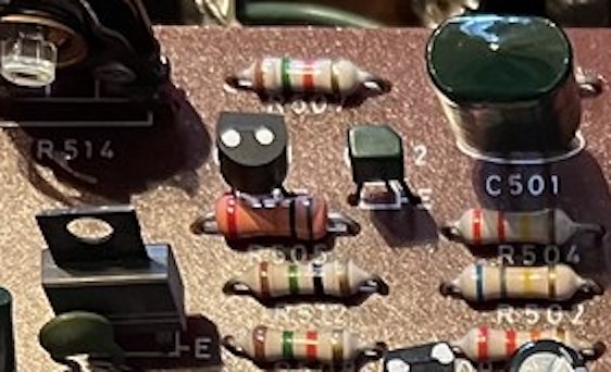
One thing I have noticed is Q601 and Q603, which are both 2SC632A, and both have two little white dots on top, which I assume was an indicator of Sony’s pair matching, both give very different readings.
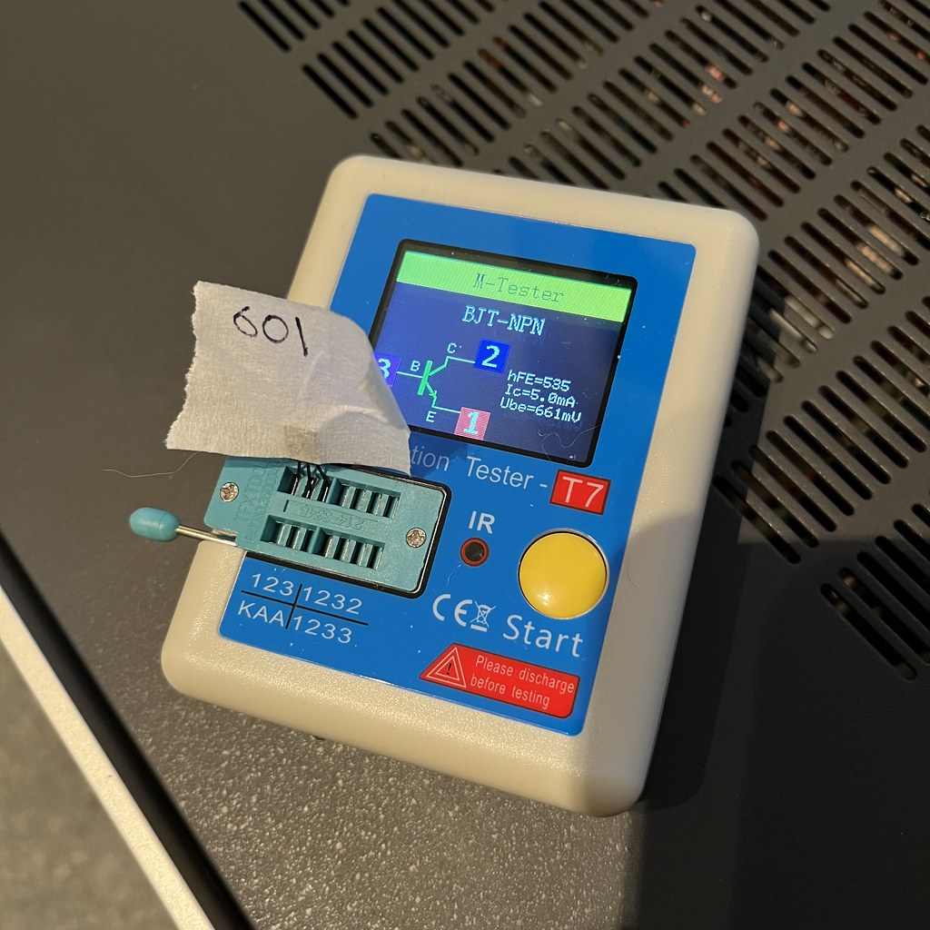
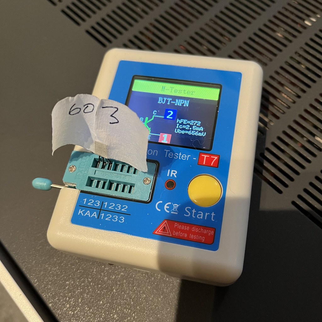
I don’t know what I’m looking at here, I don’t understand what these parameters mean, but they look very different to my eyes.
I want to swap out every transistor on this board. As soon as I’ve got a full substitution list together I’ll get an order in. The black corrosion on the legs along with discrepancies such as the above suggests they all just need to go in the bin.
One thing I have noticed is Q601 and Q603, which are both 2SC632A, and both have two little white dots on top, which I assume was an indicator of Sony’s pair matching, both give very different readings.
I don’t know what I’m looking at here, I don’t understand what these parameters mean, but they look very different to my eyes.
I want to swap out every transistor on this board. As soon as I’ve got a full substitution list together I’ll get an order in. The black corrosion on the legs along with discrepancies such as the above suggests they all just need to go in the bin.
")