
You are using an out of date browser. It may not display this or other websites correctly.
You should upgrade or use an alternative browser.
You should upgrade or use an alternative browser.
Colin Wonfor's SECA amp build
- Thread starter Marra
- Start date

Hi Keith
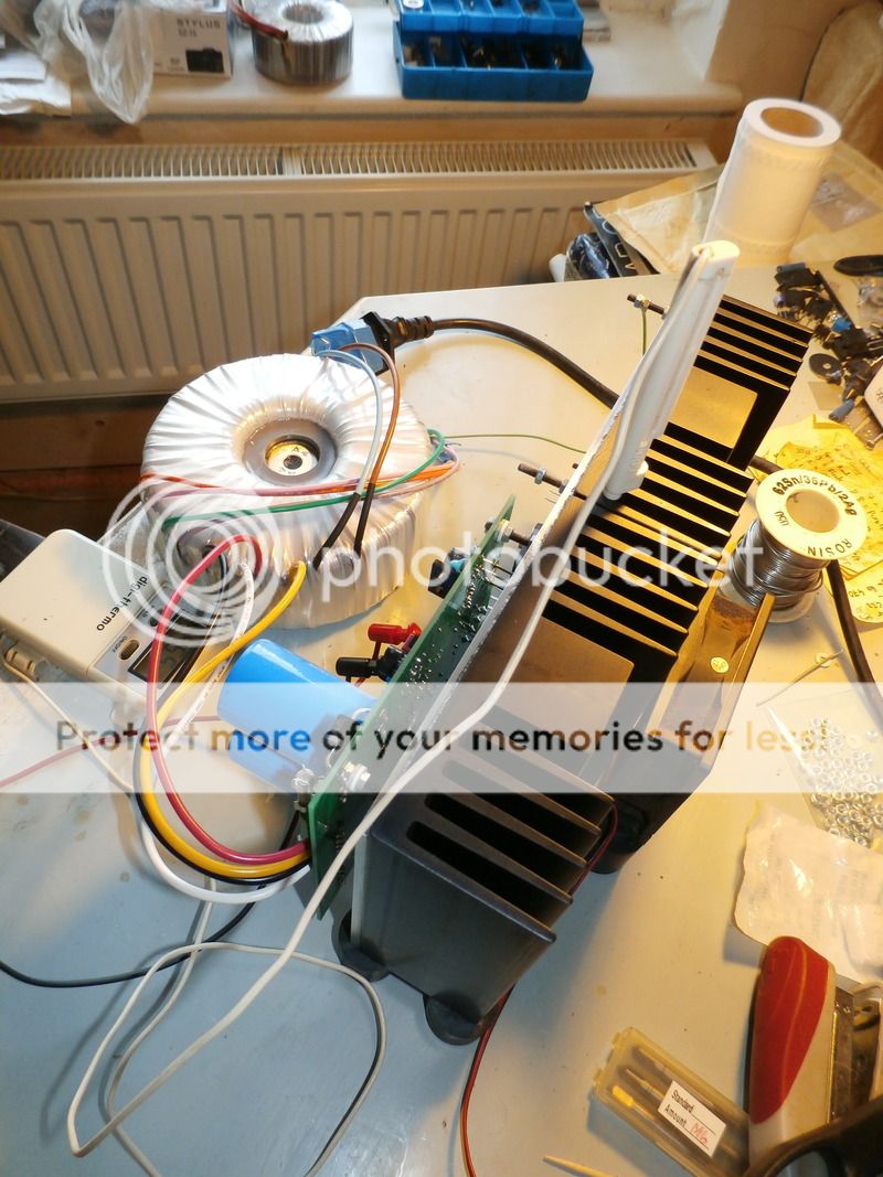
I drilled the copper out first and then used it as a template to mark, drill and tap the heatsink.
The first one took a little time but the second was a little faster.
I also used some L extrusion to get max pressure between copper and heatsink.
The copper is untapped to give a sort of vice effect between heatsink and bracket.

Hi Colin
yes I've seen that beastie on another forum and was wondering if you have it venting hot air out or blowing cold air in?
When I start work on the Chassis I'm planning on the fan dance but TBH @ 2.1A he's running warm rather than hot. (yes I've checked the copper and it's running at around the same).
the heat is spread much more evenly across the sink which is nice.
On the fan
I'm wondering about setting it up to blow onto the heatsink fin side rather than breathing over those small signal transistors.
any thoughts welcome.
''Nice work''
scruffy but sounding great. but the work is mostly yours.
This fan blow in a 24V DC fan a single diode rectifier and Bulk cap chosen to run the right speed very slow, and by trial and error. Heatsink run cool at 2.1A about 17-18C above ambient.
You are feeding the fan 10ish V from what I've read. any chance of posting the little PSU circuit for that?
I think that I may go the lazy way and use a variable reg to adjust the fan speed.
one of those little maplin jobs should manage fine and I have a few in my parts box.
elegant nope
quick for experimenting yes
PigletsDad
My intelligence test came back negative.
You could go a step further, and vary fan speed to stabilise the heatsink temperature; fan would be off until heatsink gets to target temperature, than run faster on hot days and slower when cold.
You could go a step further, and vary fan speed to stabilise the heatsink temperature; fan would be off until heatsink gets to target temperature, than run faster on hot days and slower when cold.
Great Idea and one worth looking into
my music room is in a new build out building and has super efficient insulation which is great for the spring, autumn and winter but in the summer it runs hot even with the windows open.
Now if anyone has a circuit for a heat controlled fan then that would be a useful thing to add to this thread.
Keith
Ive added the BA-3 FE Pre to my system today and its really a great match for the SECA as you mentioned. Big beefy firm and fruity.
Huge soundstage and great clarity for those who like a little gain.
2 x 20V 80VA transformers, 2 x simple 317/337 regs and 50K DACT all from the parts box. So a try out build but Im thinking that it deserves better. I may try the super regs and a nice new case next for a Fugly
special build.But sounding superb as is.
and well worth the outlay.BTW
The BG-N in the SECA made a nice difference in terms of clarity and a mid-range to die for. I have a used Mundorf MKP in the BA-3 so keeps my efforts to use different cap types in the signal path intact.
Thanks for the heads up on that.
Youre very generous with what you know.
Im a very, very happy camper.
Glad that you like the BA3 pre Shaun as you say detailed;dynamics and a big soundstage
I wonder how it would sound with a pair of LesW's VBE's powering it.
The One4 has been dismantled; heatsinks drilled and tapped ready for the power supply and copper heat spreader which is on it's way as are the transformers which LesW has very kindly dispatched( thank you Les)
I wonder how it would sound with a pair of LesW's VBE's powering it.
The One4 has been dismantled; heatsinks drilled and tapped ready for the power supply and copper heat spreader which is on it's way as are the transformers which LesW has very kindly dispatched( thank you Les)
Looking good Keith.
Sounding good also.
I must admit that I hated the drilling and tapping part (and so did my fingers) but its just a necessary evil for the sound reward.
The copper seems to be running the sinks a little more evenly which helps things so a little time and cash well spent IMHO.
Looking forward to your thoughts one the regs are fitted.
Sounding good also.
I must admit that I hated the drilling and tapping part (and so did my fingers
) but its just a necessary evil for the sound reward.The copper seems to be running the sinks a little more evenly which helps things so a little time and cash well spent IMHO.
Looking forward to your thoughts one the regs are fitted.


Nice work Keith and even more irritating to see that the quality of your craft makes my efforts look pretty duff.
doing a worse job will make me feel better so a little less effort please
Are you finding the heat is being dispersed over the sink a little more efficiently with the copper fitted?
What bias setting (just noticed 2A on the Fluke)? Ambient temperature?
Looking forward to your thoughts.
doing a worse job will make me feel better so a little less effort please
Are you finding the heat is being dispersed over the sink a little more efficiently with the copper fitted?
What bias setting (just noticed 2A on the Fluke)? Ambient temperature?
Looking forward to your thoughts.
quickie
pfm Member
How did you implement your Case fan?
Like this :
Pic is of 80mm fan, but a 120mm running @ 5v worked really well.
Very little wind noise, just the vibration to deal with, which can be minimised with some rubber mounts, or bands like Colin has done.
I don't about that Shaun as I have basically copied yours. You must have known
The second copper bar has had to have elongated holes in some places
What is it they say; measure twice; cut/drill once. I'm afraid I got it a--e about face with the second one.
and I made it up as I went along
I found it pretty tricky to line up all of those holes TBH so you are not alone on that.
Nearly cooking with gas Keith.
Hi Quickie
I was wondering about fanning the fins but its tricky (err quickie
) as unless firmly secure the fan is going to want to oscillate wildly.I would usually go for sorbothane mounts but then we have the heat factor to consider so maybe Colin’s method with the silicon rubber O rings may be the best solution.
also
Maybe building a false base into the chassis and fitting the fan there may also be good as the air flow can be directed over the fins something in the style that PD mentioned earlier in this thread.
No rush on that as the temp outside is dipping.