advertisement


Best CD clock upgrade?

hacker said:
I hear what you're saying guys, but others shouldn't have to pay for my **** up...

Hi Carl,

Nobody paid for your time, so it's the least we can do to pay for your "fu*& up". If anybody whinges over a few pence they don't deserve to be part of the group buy!

Regards,

Mus
 
Cockup #2 (this is getting embarrasing):

Resistors R10 and R11 are, for some reason, specced as normal MRS25 resistors on my spreadsheet but the PCB has space for SMD components. This means that I've had to order a bunch of 100R and 33R SMD resistors, too. They'll arrive tomorrow (allegedly).

Tomorrow night could be a late one, now that I'm swapping 2 resistors and a cap! At least I've noticed the mistakes before sending the stuff out!!!

Bugger, damn and blast, I'm off to hang my head in shame...

Andy, I can see why you stopped doing kits with your superregs ;)

Carl
 
I see what your saying Carl but didnt some of us review your speadsheet (cant remember if looked, honest;))

Anyway, I'll take two of those 3.3uf caps from you, let me know what I owe and I'll bank transfer the big money :D

Can't think what I could use those resistors for though, how much did the SMDs cost you Carl?
 
hacker said:
Ok, thanks Oz, I can do that but I can't post tomorrow (Tuesday) as I'm out on business at a client all

yeah yeah what makes me think mr cant stop hacking is going to be listening to his new clocked CD3.5 first, youre sooooooo at it ;)
 
but others shouldn't have to pay for my **** up

Actually Carl, I take full responsibility for this, it's my mistake in speccing the components in such a hurry (whilst trying to re-use types where possible to save costs).

My apologies, and if it causes any particular problems, I'll help to sort them out.

Thanks though to all the generous responses above, that's what makes this place so great, (and you are all getting an exceptional product for a great price ;) ).

Just look at the price of commercial clocks...

Andy.
 
Andrew L Weekes said:
Actually Carl, I take full responsibility for this, it's my mistake in speccing the components in such a hurry (whilst trying to re-use types where possible to save costs).

Generous to take the blame, however I was buying the parts and should have checked more thoroughly... and you certainly can't take the blame for getting the wrong resistors! That was done, as you say, trying to get the best deal by buying in bulk.


Andrew L Weekes said:
Thanks though to all the generous responses above, that's what makes this place so great, (and you are all getting an exceptional product for a great price ;) ).

You're right - thanks to all for being understanding and patient! It's worth it in the end, I promise...

trancera said:
yeah yeah what makes me think mr cant stop hacking is going to be listening to his new clocked CD3.5 first, youre sooooooo at it ;)

Erm, guilty as charged!

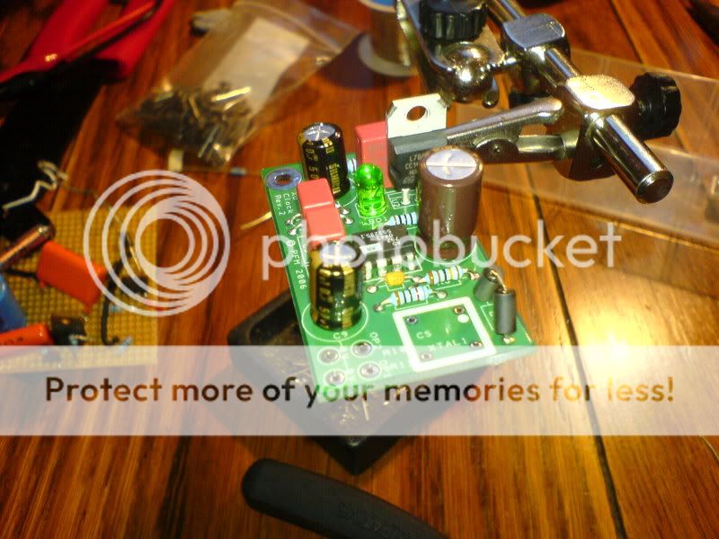
The flea being built (I used silmics cos I've got 'em):

w_dsc00487.jpg


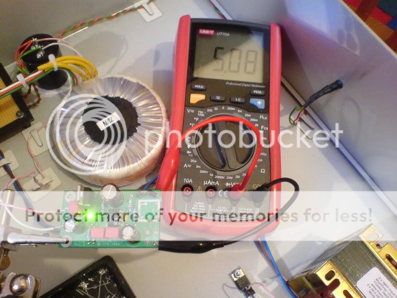
I remembered to check the output voltage before installing the XO module ;)

w_dsc00488.jpg


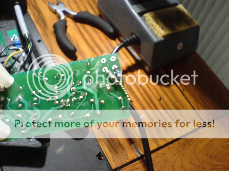
The 100R/33R SMD resistors won't be here until tomorrow so I used regular resistors and twisted them together at one end, then twised the output pin of the tent XO around them. I soldered it together for a really nice connection:
w_dsc00490.jpg


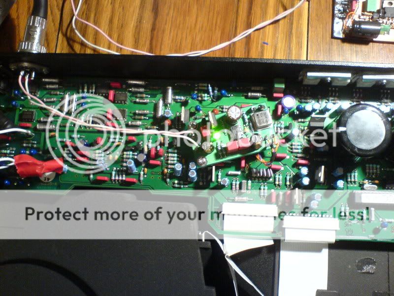
Now it's in the cd3.5 making music :D My girlfriend has friends getting drunk in the livingroom at present... "turn it down we're trying to talk..." so I don't really know what sounds like yet, but it certainly works!
w_dsc00493.jpg


Don't worry, you'll have yours soon!!!
Cheers,
Carl
 
We just new you were itching to get this going ;)

One tip, it might be worth trying to arrange two short wires coming from the CD motherboard clock connections, straight into the clock o/p connections (i.e. lower the clock board onto them from above, then solder them, with a view to making them as short as is physically / practically possible.

I'd suggest leaving the pins out of those clock output connections when building, if it's practical to do the above.

Andy.

P.S. Also if anyone powers this from an internal PSU supply (the analogue supply on a CD5 is ideal for this especially if you have an external PSU for the o/p stage [and it's available, via a via in the PCB, at just the right location ;)]), only connect the output ground pin, close to the DAC chip, leave the i/p ground pin unconnected.
 
The caps arrived today, but not the 100R/33R SMD resistors. Looks like another day's delay folks - I'm really sorrt about this, rest assured I'll get the kits out asap.

On a different note, in a cd3.5 the flea can be used to power not just a clock, but also things like a DAC...

...and that's just what I'm planning. Martin/Andy, can I run this by you for an idea: I want to remove the 3.3R resistor that links the DAC +vin pin to its power source and replace it with the output of a flea. The +ve input of the flea reg will be taken from one of the external analogue psu rails and the 0v of the flea will be connected to the cd3.5's ground plane (near the DAC).

I'm wondering if it's best to put a little series R between the flea and the DAC, to keep things stable? Also wondering what difference there would be with/without L1 on the flea?

Cheers,
Carl
 
Carl that works just fine as discussed the other day. There's no strict need for L1 - that's mostly to restrict noise from the clock - and in fact since this is an analogue audio path I'd suggest getting rid of the ferrite would be a good thing.

Keep an eye on the current drawn (monitor voltage across the 0.5R) and if the current gets much above 30mA the flea probably oscillating - the TDA1305 output stage only draws 6-10mA, about the same as the TENT XO, so you should see comparbale numbers.
 
martin clark said:
Carl that works just fine as discussed the other day. There's no strict need for L1 - that's mostly to restrict noise from the clock - and in fact since this is an analogue audio path I'd suggest getting rid of the ferrite would be a good thing.

Keep an eye on the current drawn (monitor voltage across the 0.5R) and if the current gets much above 30mA the flea probably oscillating - the TDA1305 output stage only draws 6-10mA, about the same as the TENT XO, so you should see comparbale numbers.

Great. Would some series R help keep things stable? Just an ohm or two?

Aslo just wondering again about psu arrangements... is it best to take a feed from the external analogue psu and run the 0v wire (only one) from flea to the star 0v used by the analogue psu/SRs or would it be better to run the flea's 0v wire to the ground plane near the DAC?
 
Great. Would some series R help keep things stable? Just an ohm or two?
No, it should work just fine. Keep the local decoupling cap at the dac PSU pins, too. Just watch the current, and if it seems high, then try a small amount of series R.

is it best to take a feed from the external analogue psu and run the 0v wire (only one) from flea to the star 0v used by the analogue psu/SRs or would it be better to run the flea's 0v wire to the ground plane near the DAC?
Run it to the ground plane close to the dac's power pin supplied - ideally at the 0V connection of the local decoupling cap. Use a pair of wires lightly twisted together.

The other way makes the ouput loop huge - since it includes the distance between the analogue star and the dac - and that would be a positive invitation to noise and instability problems.
 
martin clark said:
No, it should work just fine. Keep the local decoopling cap at the dac PSU pins, too. ustt watc the current, and if it seems high, then try a small amount of series R.

Ok, cheers. I'll do that.

martin clark said:
Run it to the ground plane close to the dacs power pin supplied - ideally at the 0V connectiuon of the local decoupling cap. Use a pair of wires lightly twisted together.

The other way makes the ouput loop huge - since it includes the distance between the analogue star and the dac - and that would be a positive invitation to noise and instability problems.

Uh, yeah. Do I feel silly now! Sometimes the obvious is staring you in the face...
 
I've hooked up another flea to the DAC and measured the voltage across the 0R5. I get 7.5mV which makes the current draw 3.75mA by my calculations... does that sound about right?

I also settled on using a 0R5 in series with the output because I've got 6.6uF of film caps (nothing else) decoupling Vin of the DAC and I wanted to ensure stability.

Carl
 
That's 15mA, spot-on I'd say. Don't be afraid to try it without the series R though - oscillation would be signalled by the current increasng disproportionately (say >>30mA / 15mV)
 
Carl,

You can do what ever you like with the Finland pack. Just take your time if you have to change resistors, too. No hurry.

...Or how was it sorted out? Did not read everything..


Oz
 
Finally, the interminable wait has ended... all the parts are here :D My girlfriend just called from home to say that the last package (SMD 100R and 33R resistors) has arrived.

That means I'll be putting packages in the post from tomorrow onwards, although I'm not promising to get them all out tomorrow! I'll do my best though, many thanks for your patience everyone.

It really will be worth the wait, as the results of this circuit speak for themselves. I've got one flea+XO for my clock and one bare flea powering the DAC in my cd3.5 and it really is very, very good indeed :D

Some of you bodgers will have an interesting and enjoyable weekend!

Carl
 
It really will be worth the wait, as the results of this circuit speak for themselves. I've got one flea+XO for my clock and one bare flea powering the DAC in my cd3.5 and it really is very, very good indeed
Glad to hear it!
Some of you bodgers will have an interesting and enjoyable weekend
And the build manual and photos to assist will appear in a new thread v.soon.


advertisement


Back
Top