
You are using an out of date browser. It may not display this or other websites correctly.
You should upgrade or use an alternative browser.
You should upgrade or use an alternative browser.
Avondale NCC300 Monos Underway
- Thread starter Mike Hanson
- Start date
Mynamemynaim
38yrs a Naim owner
Appreciate it doesn't sound like much...but when you then bring it up to the same volts level as the other amp....the mA current draw rises quite significantly in comparison for some reason?
If others think it's ok ( and it certainly sounds it) I'll just stick with the matching mA reading and forgot about it
Thanks
If others think it's ok ( and it certainly sounds it) I'll just stick with the matching mA reading and forgot about it
Thanks
Gervais Cote
Predator
100 hours of break in period is common with many audio products : amps, speakers to name a few.As for breaking in, my M180-300s took about 4-5 weeks with 3 hours / day usage, so 100 hours+. Stereo picture suddenly improved and bass power became more apparent
337alant
Negatively Biased
Yes I agree, then I whip the top off and re-check all the voltage readings, DC offset and Bias again then its good to go.100 hours of break in period is common with many audio products : amps, speakers to name a few.
Alan
Luca
pfm Member
As for breaking in, my M180-300s took about 4-5 weeks with 3 hours / day usage, so 100 hours+. Stereo picture suddenly improved and bass power became more apparent
The same is happening to my amp (with Qudos boards inside) that started playing six weeks ago.
S-Man
StrivingON
I have an issue that to be honest...I've been trying to ignore...but it keeps coming back to mind to brother me
When I set the bias...I can set both amps to the same mA settings for current draw
Or
I can set both amps to the same voltage across the resistors
But I cannot set both amps to have similar current draw and voltage??
One reads approx 120mA and 1.196v
The other reads 120mA and 1.148v
Why would that be when the component values and importantly the (regulated) DC input voltage are the same?
Is this something I should be worried about?
Should I set the amps for the same draw or the same volts (assuming I cannot correct the problem)
The amps sound great as is...but that doesn't stop this bothering me
Any thoughts anyone please?
Current is what matters.
The voltage you need to achieve the correct quiescent current depends on the Vbes of the drivers and output devices, which is temperature dependent.
I have no idea why people people started specifying the VBe multiplier voltage. The only reason is to measure this is to set it at minimum before intial power up.
In conclusion - you should not be worrying about the voltages at all!
The only other thing that might be of concern is that output devices are sharing current nicely. Just measure the voltages across all 4 emitter resistors. If you want 60mA per device then approx 13mV across each 0.22R is the target (depends on the value/tolerance of the resistors).
Mynamemynaim
38yrs a Naim owner
Thanks @S-Man
I was hoping it was just due to tolerance stacking and something I shouldn't even be worried about
The rehash of my preamp seems to have brought even more out of the '300s and I'm genuinely amazed and smiling every time I hit play
Even recordings that sounded a bit naff before (like David Bowie's Glastonbury set ) now sound different and much more.listenable to
There's just a genuine magic to these amps
Anyway...I'll carry on listening till I decide to recheck the settings...and maybe wind the bias up a bit more (to say 150mA) as they are hardly getting warm really
Mynamemynaim
38yrs a Naim owner
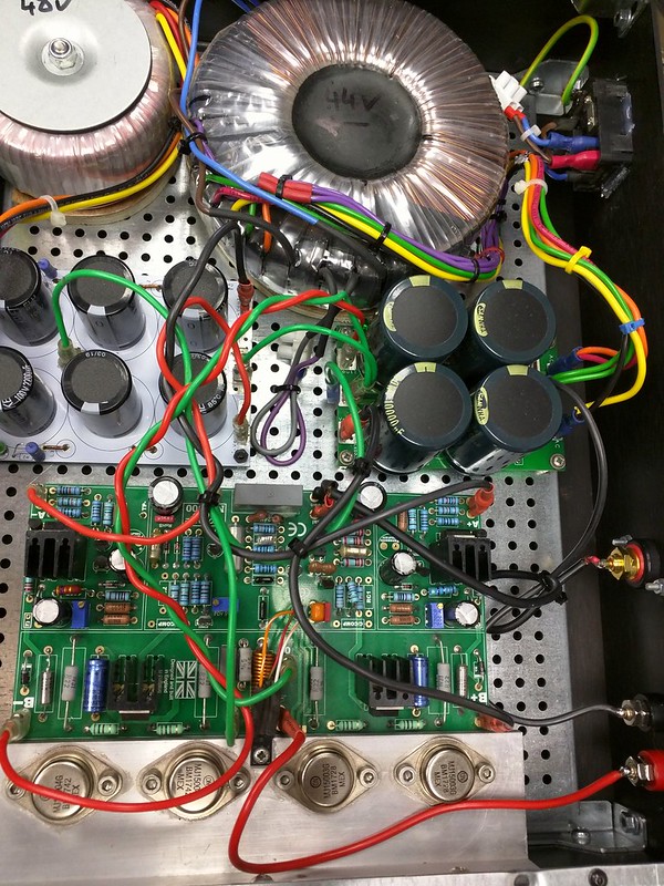
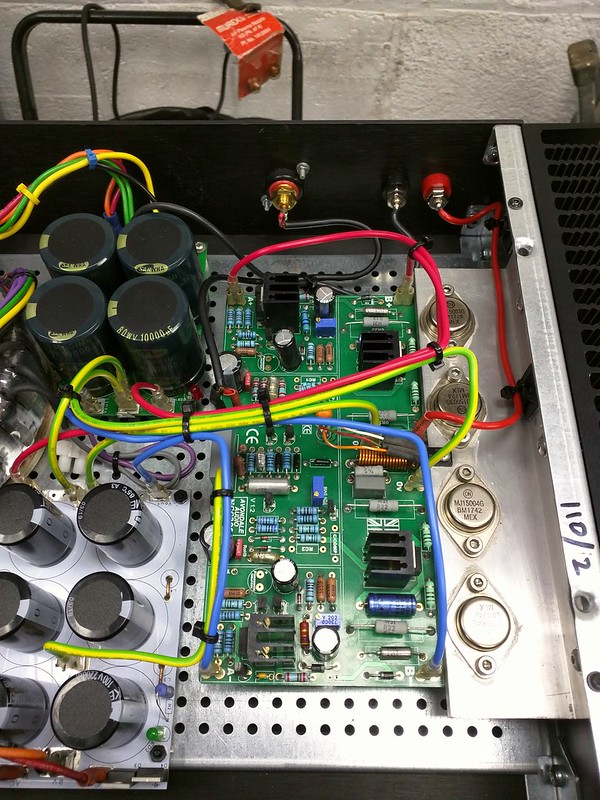
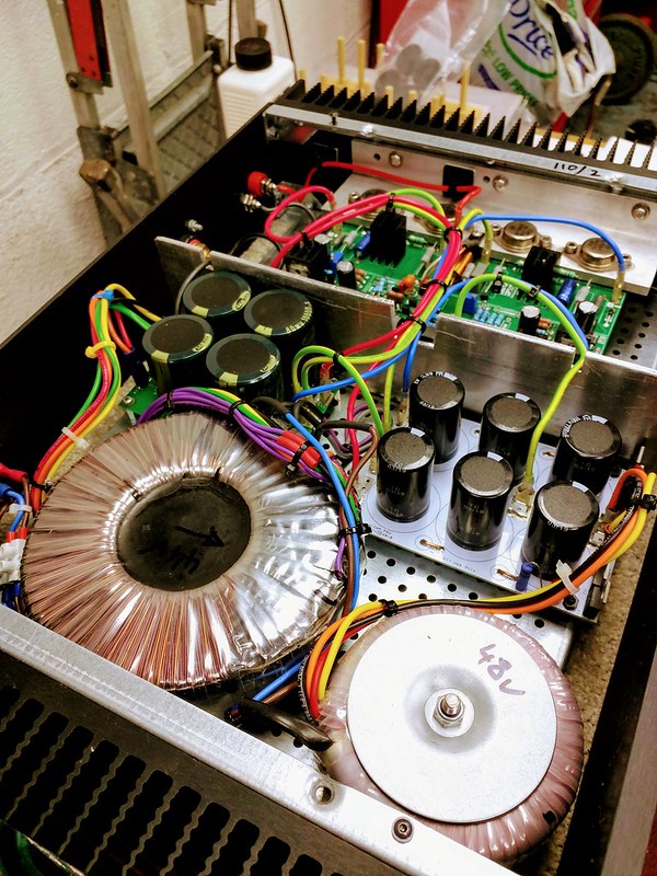
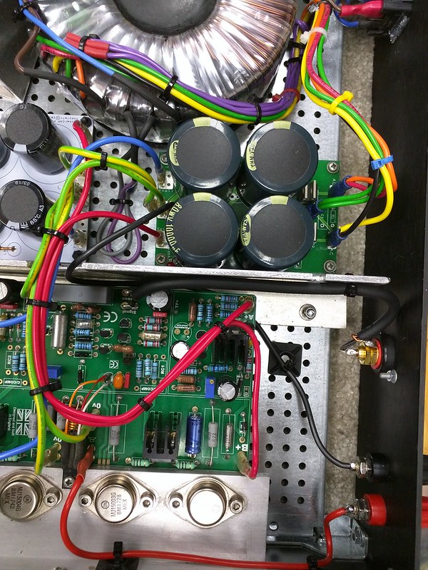
"inspired" (shamed!!) by the recent neat wiring thread, I thought I would make a half hearted effort to tidy up my mono's
I'm not saying this is much of an improvement ...but I'm a little happier (All new silicone wiring to boards and some of those self adhesive cable anchors to) as its a bit more "logical" now (red for positive, blue for negative voltages)
Before and after....
 [/url]2021-09-10_05-32-35 by rock solid, on Flickr
 [/url]2021-09-10_05-33-06 by rock solid, on Flickr
 [/url]2021-09-10_05-33-52 by rock solid, on Flickr
 [/url]2021-09-10_05-34-22 by rock solid, on Flickr
PS
While they are on the bench, I plan to make an aluminium screening plate between the power supplies and the board and loose the wood under the TX and replace with thick rubber....I'll share a picture if it comes out ok
I'm not saying this is much of an improvement ...but I'm a little happier (All new silicone wiring to boards and some of those self adhesive cable anchors to) as its a bit more "logical" now (red for positive, blue for negative voltages)
Before and after....
PS
While they are on the bench, I plan to make an aluminium screening plate between the power supplies and the board and loose the wood under the TX and replace with thick rubber....I'll share a picture if it comes out ok
Mynamemynaim
38yrs a Naim owner
It looks like you have connected the signal 0V to the middle of the cap bank, instead of the "clean" end.
If that's the case, is there a reason?
In fairness Laverda pointed out the same thing earlier (for the speaker negative)...and I just couldn't bring myself to believe there was a "dirty" and "Clean" end of an 8cm straight copper circuit board track?
Am I completely wrong in this? it just defies logic to me...
Edit ...Ive got nothing to loose in changing it I guess...I will tomorrow
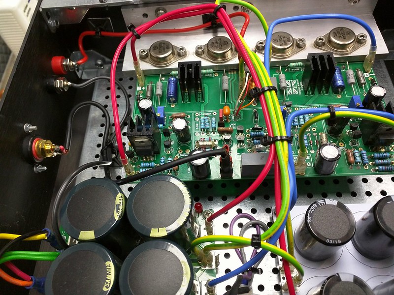
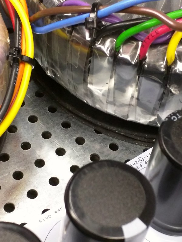
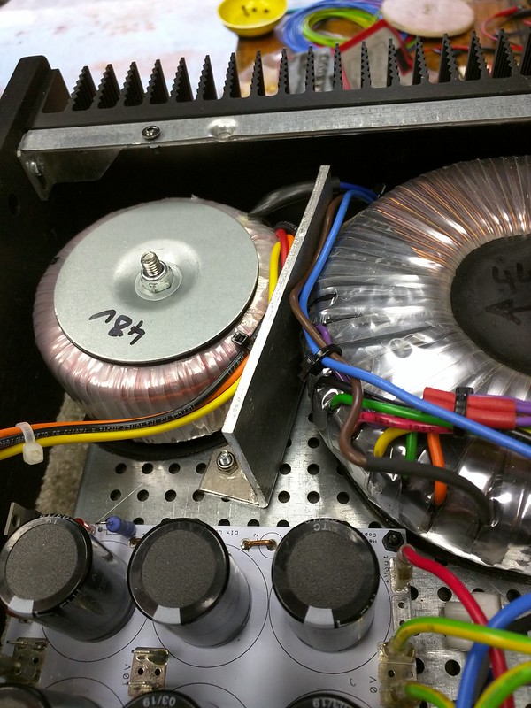
Anyway ... I've put several thin sheets of rubber under both transformers, and removed the wood
I've also made a 3.2mm alloy "shield" for the motherboard (and in the process of making another to go between the two Tx's
The rubber seems to have reduced the buzz from the transformers (I have an isolation transformer on my mains...so don't think it is DC on the mains)
I've also cleaned up the wiring a little more since these pictures
PS
One bonus of the shield in the case is that the whole base board is now much more rigid!!
Mynamemynaim
38yrs a Naim owner
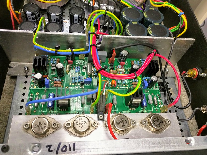
Finally fed up with mods!! Time for some listening
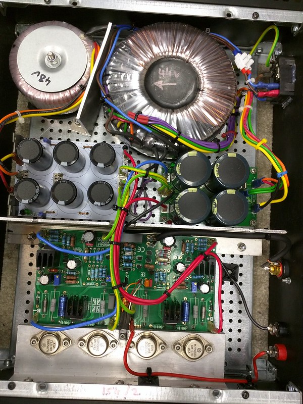
I've taken on board others advice (thanks @laverda and @S-Man ) and changed the returns to the "clean" ends of the power supplies
Also finished the shield for the two transformers (well as best as they can be shielded in the space available)
The wiring is now somewhere near what it should have been when I first did it though as I look at the pictures I still think...why didn't you route that wire another way...but its a big step up on how it was initially
and its also a shame I didn't think about shields etc when I planned the layout....ohh well
Now to see if it all makes a difference
 [/url]2021-09-12_03-41-10 by rock solid, on Flickr
 [/url]2021-09-12_03-41-51 by rock solid, on Flickr
 [/url]2021-09-12_03-42-26 by rock solid, on Flickr
any changes to your build yet Mike? @Mike Hanson
I've taken on board others advice (thanks @laverda and @S-Man ) and changed the returns to the "clean" ends of the power supplies
Also finished the shield for the two transformers (well as best as they can be shielded in the space available)
The wiring is now somewhere near what it should have been when I first did it
though as I look at the pictures I still think...why didn't you route that wire another way...but its a big step up on how it was initially and its also a shame I didn't think about shields etc when I planned the layout....ohh well
Now to see if it all makes a difference
any changes to your build yet Mike? @Mike Hanson
Gervais Cote
Predator
Your "after" version is the way to go in my book, this makes it impossible to a wire to touch a hot spot, melt its jacket and create a short."inspired" (shamed!!) by the recent neat wiring thread, I thought I would make a half hearted effort to tidy up my mono's
I'm not saying this is much of an improvement ...but I'm a little happier (All new silicone wiring to boards and some of those self adhesive cable anchors to) as its a bit more "logical" now (red for positive, blue for negative voltages)
Before and after....
[/url]2021-09-10_05-32-35 by rock solid, on Flickr
[/url]2021-09-10_05-33-06 by rock solid, on Flickr
[/url]2021-09-10_05-33-52 by rock solid, on Flickr
[/url]2021-09-10_05-34-22 by rock solid, on Flickr
PS
While they are on the bench, I plan to make an aluminium screening plate between the power supplies and the board and loose the wood under the TX and replace with thick rubber....I'll share a picture if it comes out ok
Gervais Cote
Predator
Love this aluminum wall for both the electrical and mechanical benefits...........some amp manufacturers should take this as an example...........In fairness Laverda pointed out the same thing earlier (for the speaker negative)...and I just couldn't bring myself to believe there was a "dirty" and "Clean" end of an 8cm straight copper circuit board track?
Am I completely wrong in this? it just defies logic to me...
Edit ...Ive got nothing to loose in changing it I guess...I will tomorrow
Anyway ... I've put several thin sheets of rubber under both transformers, and removed the wood
I've also made a 3.2mm alloy "shield" for the motherboard (and in the process of making another to go between the two Tx's
The rubber seems to have reduced the buzz from the transformers (I have an isolation transformer on my mains...so don't think it is DC on the mains)
[/url]2021-09-11_05-45-44 by rock solid, on Flickr
[/url]2021-09-11_05-44-43 by rock solid, on Flickr
[/url]2021-09-11_05-44-01 by rock solid, on Flickr
I've also cleaned up the wiring a little more since these pictures
PS
One bonus of the shield in the case is that the whole base board is now much more rigid!!
Mike Hanson
Trying to understand...
I've been traveling, etc., But I'm finally getting settled back into things. I should be resuming mine this coming week.any changes to your build yet Mike? @Mike Hanson
S-Man
StrivingON
My Nancy300s (as I tend to call them) are currently being rebuilt. I am reinstating the regs and finally getting round to fitting a cooling fan and the associated supply circuitry, which means I will actually be able to run it with the lid on!
I'm sure amps sound better with lids, if only because the "lead me not into temptation" aspect for the obsessive tweaker is reduced.
I'm sure amps sound better with lids, if only because the "lead me not into temptation" aspect for the obsessive tweaker is reduced
.Mynamemynaim
38yrs a Naim owner
S-Man
StrivingON
Was the trial not a success then?
I am not sure
.In between decommissioning and reinstating the regs I built another amp, so I have forgotten what the Nancy sounded like without the regs
.martin clark
pinko bodger
That earns a wry smile of self-recognition from me - and it's not just amplifiers..!I'm sure amps sound better with lids, if only because the "lead me not into temptation" aspect for the obsessive tweaker is reduced
Mynamemynaim
38yrs a Naim owner
It might be something as simple as more stable temperature inside an amplifier with a lid?