advertisement


Courtiestown - Naim Amplifier (Avondale) Upgrade Project

Good Morning All,

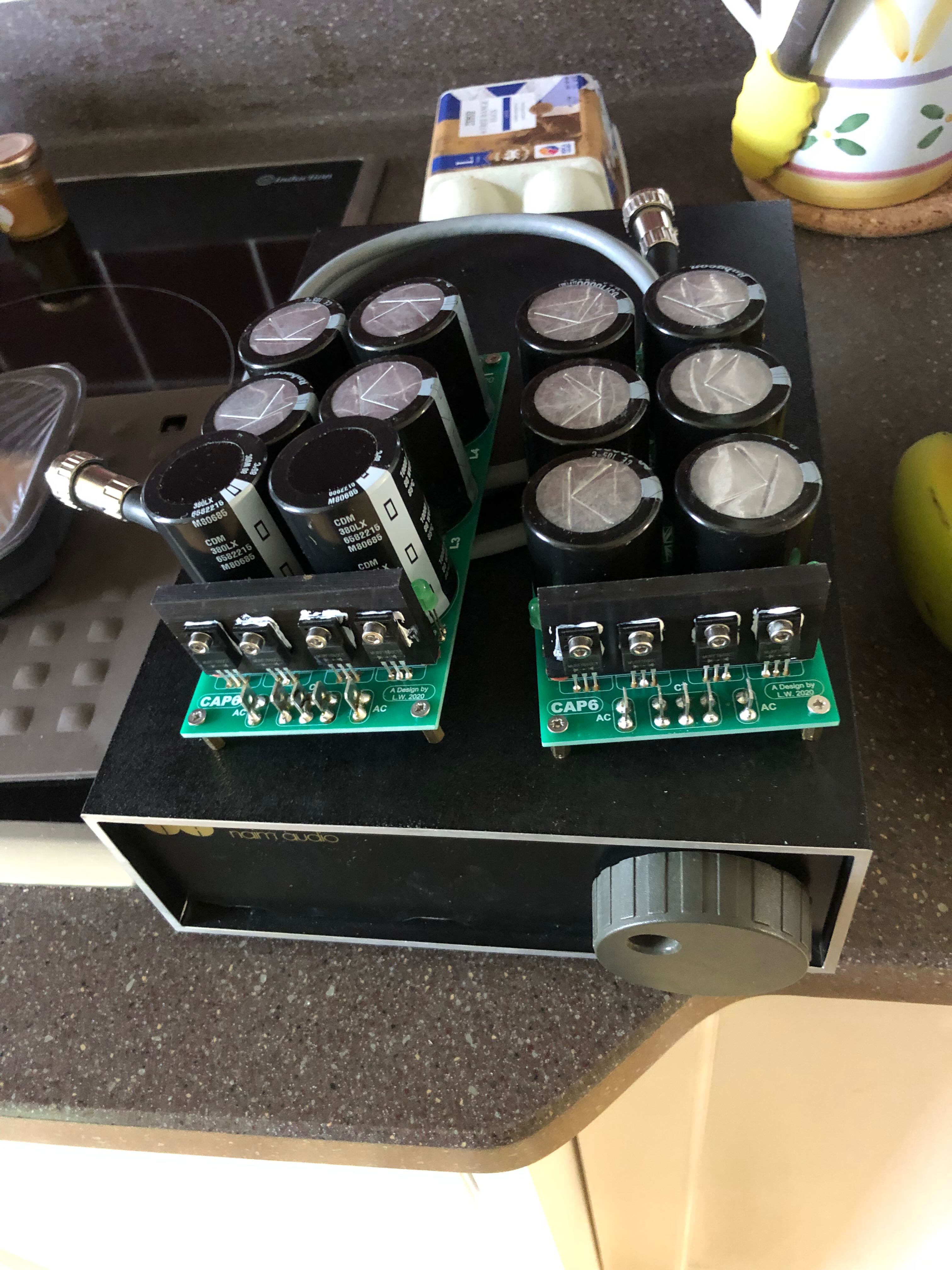
Dragged the Variac out last night to test the modified HiCap. Everything OK and putting out 24.2V. I'll leave it at this for now as I'll run the NAXO "as is" when it comes back from Salisbury and then, at some point, I'll install the ALWSR's and crank the HiCap up to 28V.

A294fAU.jpg


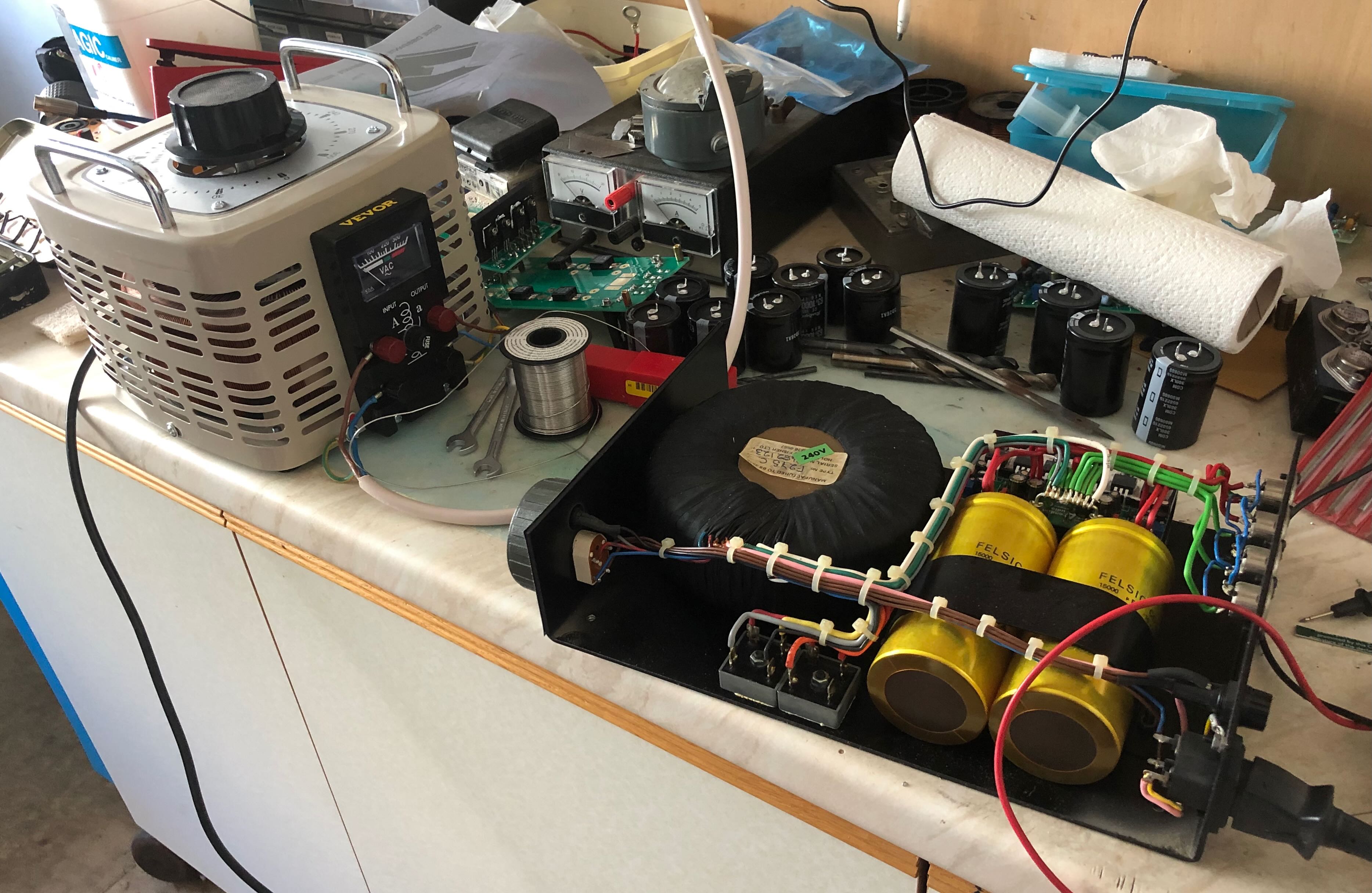
Edit - now to work out how I'm going to connect the stereo headphone socket out of the MacBook to the HiCap so that it feeds out to the NAXO............

Regards

Richard
 
Good Evening All,

It's been a productive day. First off I completed another two CAP6's:-

j1nKaIA.jpg


Next up was determining what cables I need to connect the MacBook to the HiCap, HiCap to the NAXO 2 - 4 and NAXO to the 2off stereo SE amplifiers. Order now placed with Designacable.

I started on the ALWSR's this afternoon, had to resort to some "heavy duty" tools to make the 1N5342B's fit:-

27SOo6D.jpg


Now finished 4 boards with 4 board part filled waiting on AD825's arriving:-

r93Mg0X.jpg


Regards

Richard
 
Good Morning All (again),

Just about to partially dismantle a couple of built SE board devices and change two SMD resistors to the 47R 's they're meant to be (don't ask why I installed 4k7's - a bit of brain fade).

For those that might be interested the Modushop 3U Dissipante cases came in at £216.07 each (after import duties) with anti-vibration feet and the perforated base plate.

Regards

Richard
 
Good Afternoon,

Definitely a day of one step forward and one and a half backwards.

I successfully replaced the above mentioned SMD resistors and checked bias and offsets were OK and then connected up the two modified M130's to the Sara9's and connected up the MacBook. Power up amplifiers and strange noise emanates from the left hand speaker so quick move to switch power off.

End result. Amplifier concerned, when inspected, I find I had failed to re-connect the +ive tab to the +ive terminal on the CAP6 so will need to see what didn't survive that on the PCB.

I now have no woofer output on the affected Sara9 - have dismantled said speaker. Both woofers test out 7.1 to 7.2ohms and no sign of anything obvious taken out on the crossover.

I've tried a 9V battery on both woofers, the front is a definite "thump" and the rear a definite what can only be called a "scratchy sound". Seems obvious the rear driver is no more???

Suggestions from the collective welcome.

Mainwhile scraping all old sealant off the rebate in readiness for putting things back together.

Regards

Richard
 
Good Morning All,

Replacement driver ordered off a well known internet auction site....... still it has been interesting to see how a Sara9 is built :rolleyes: 
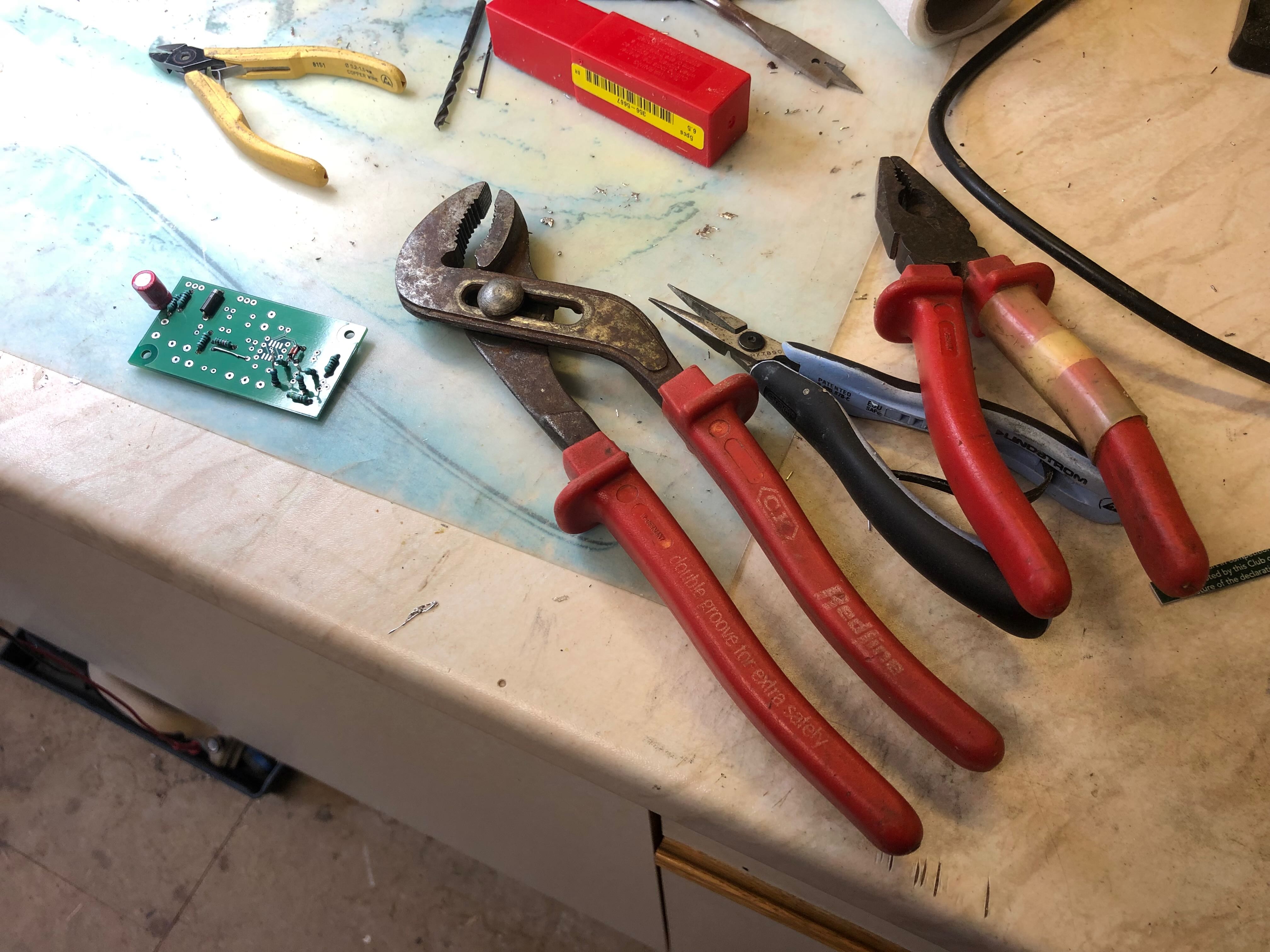
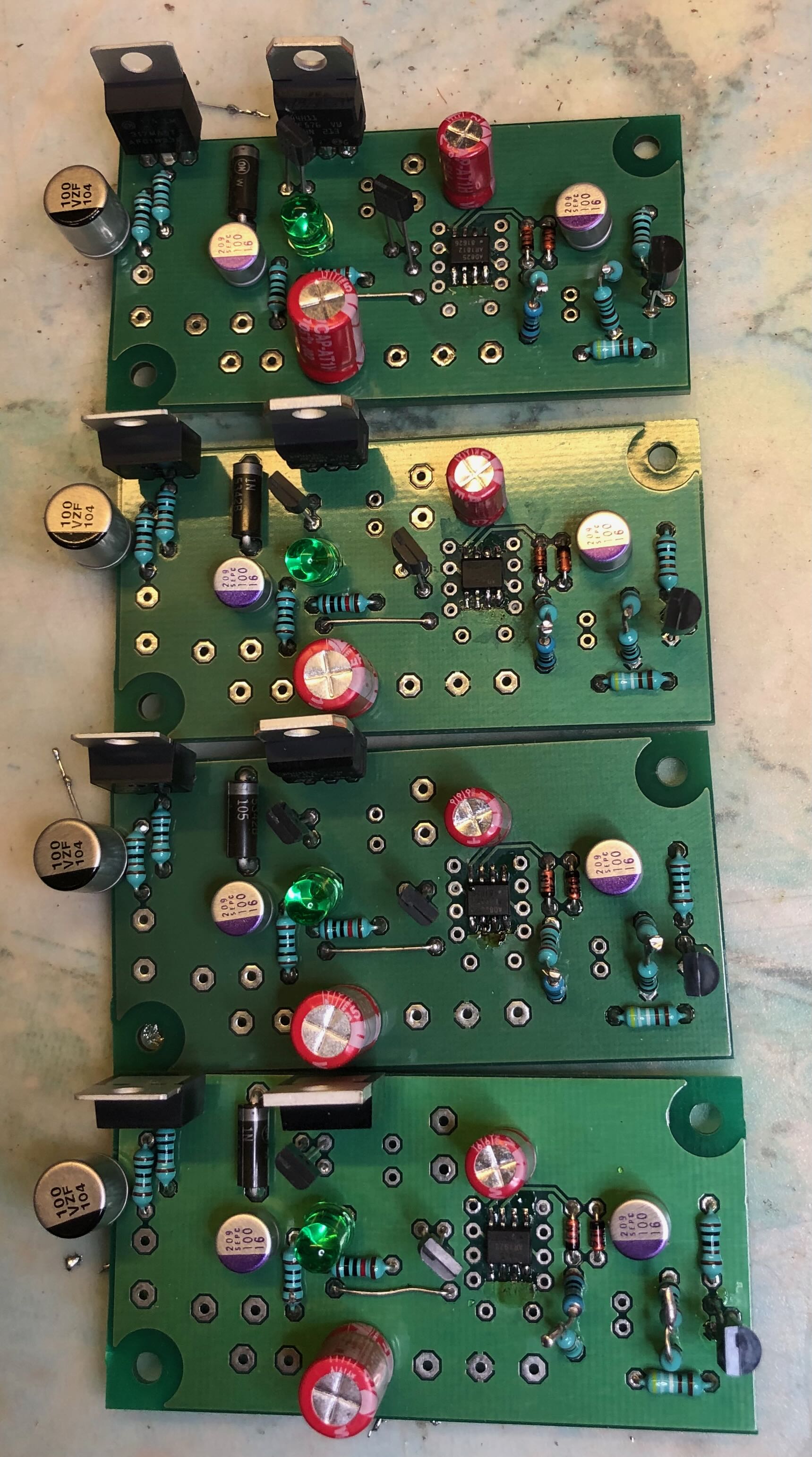
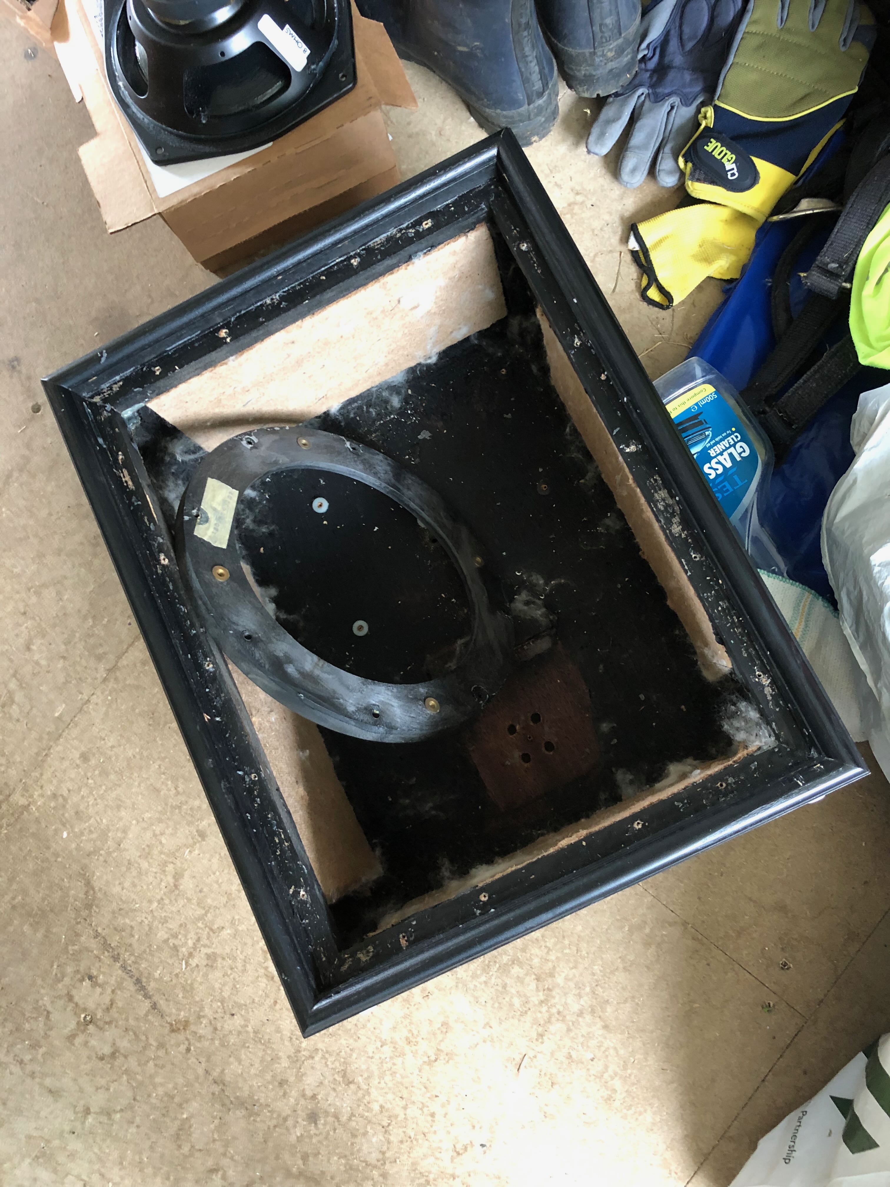
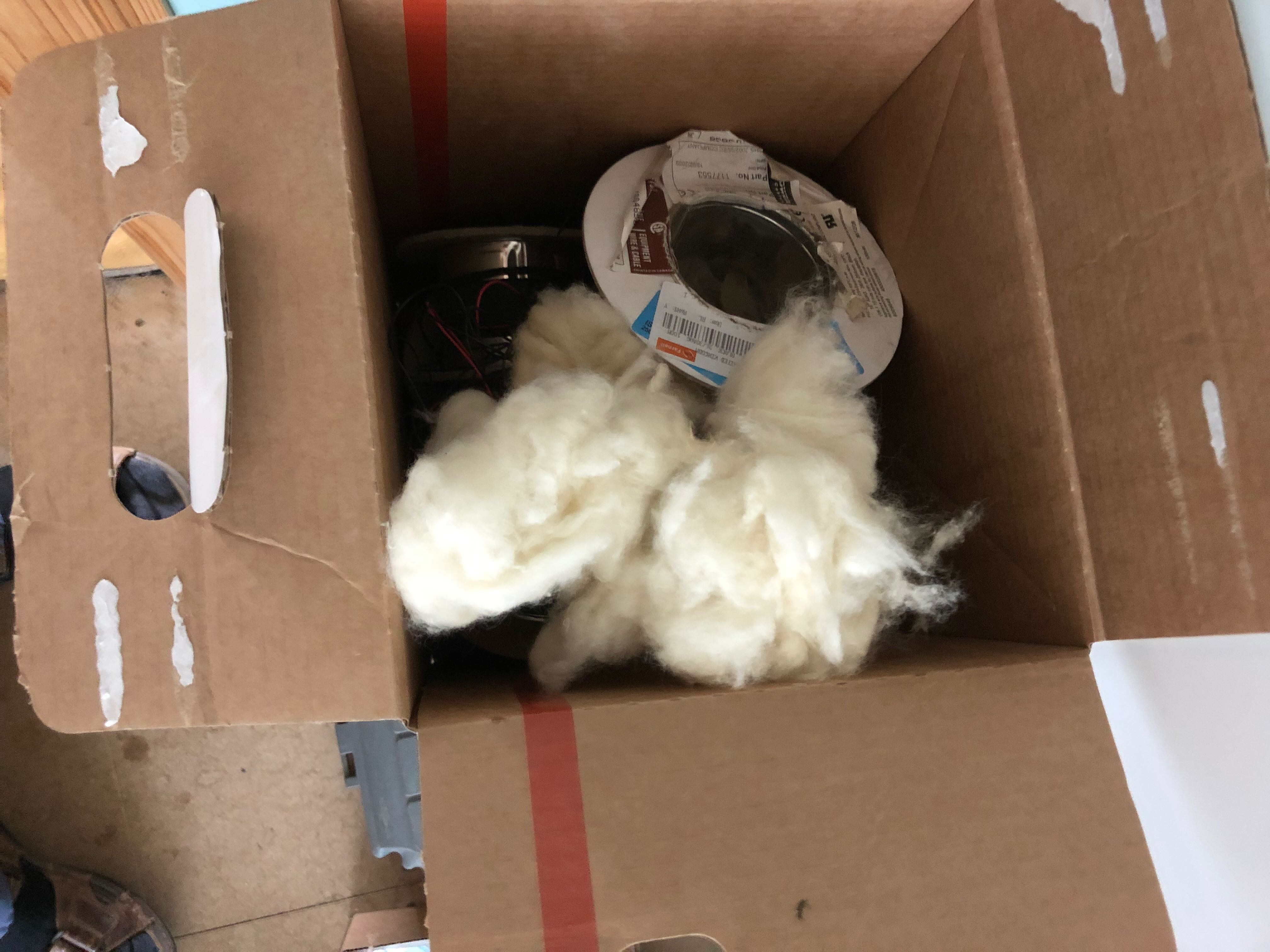
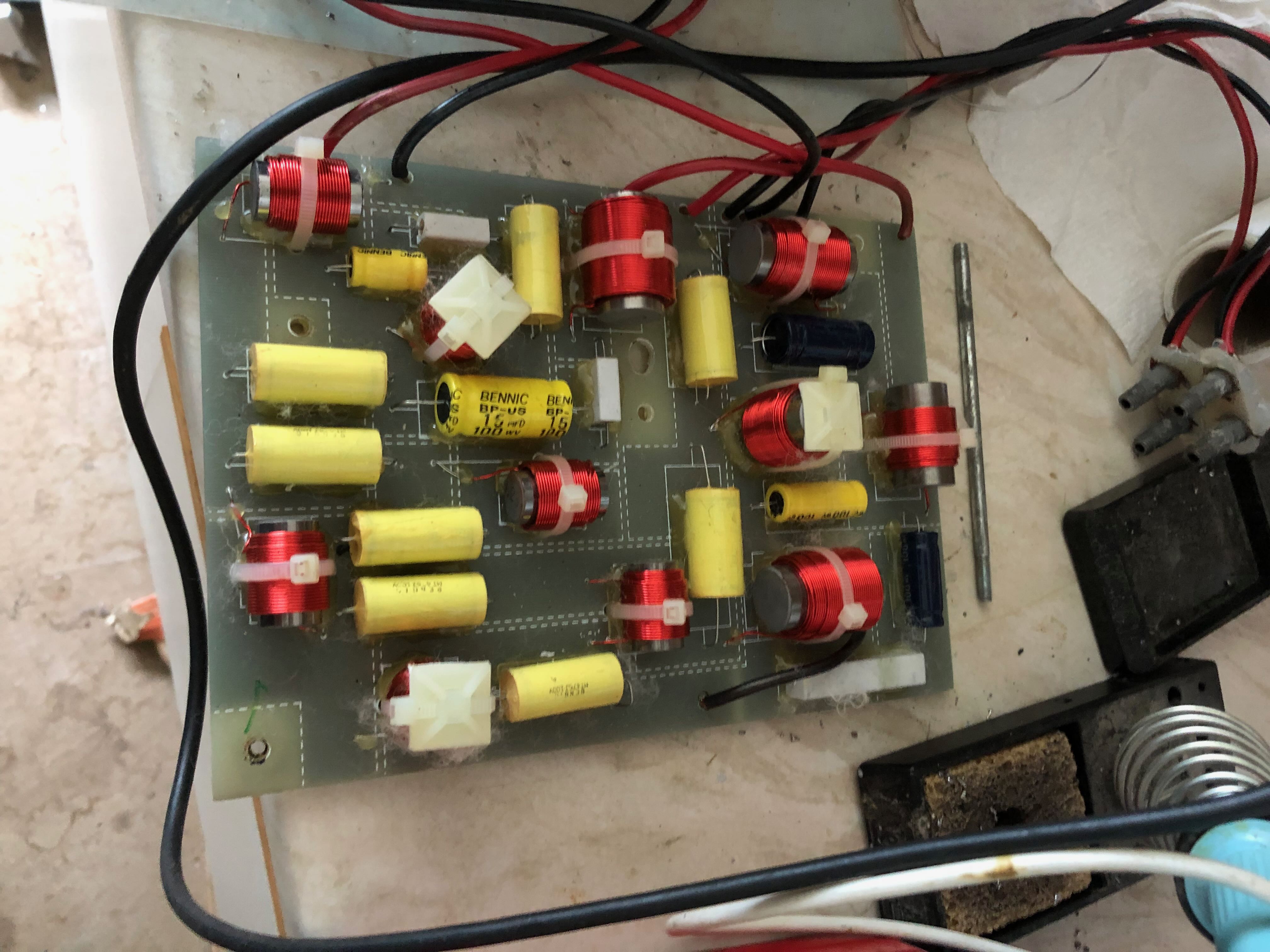
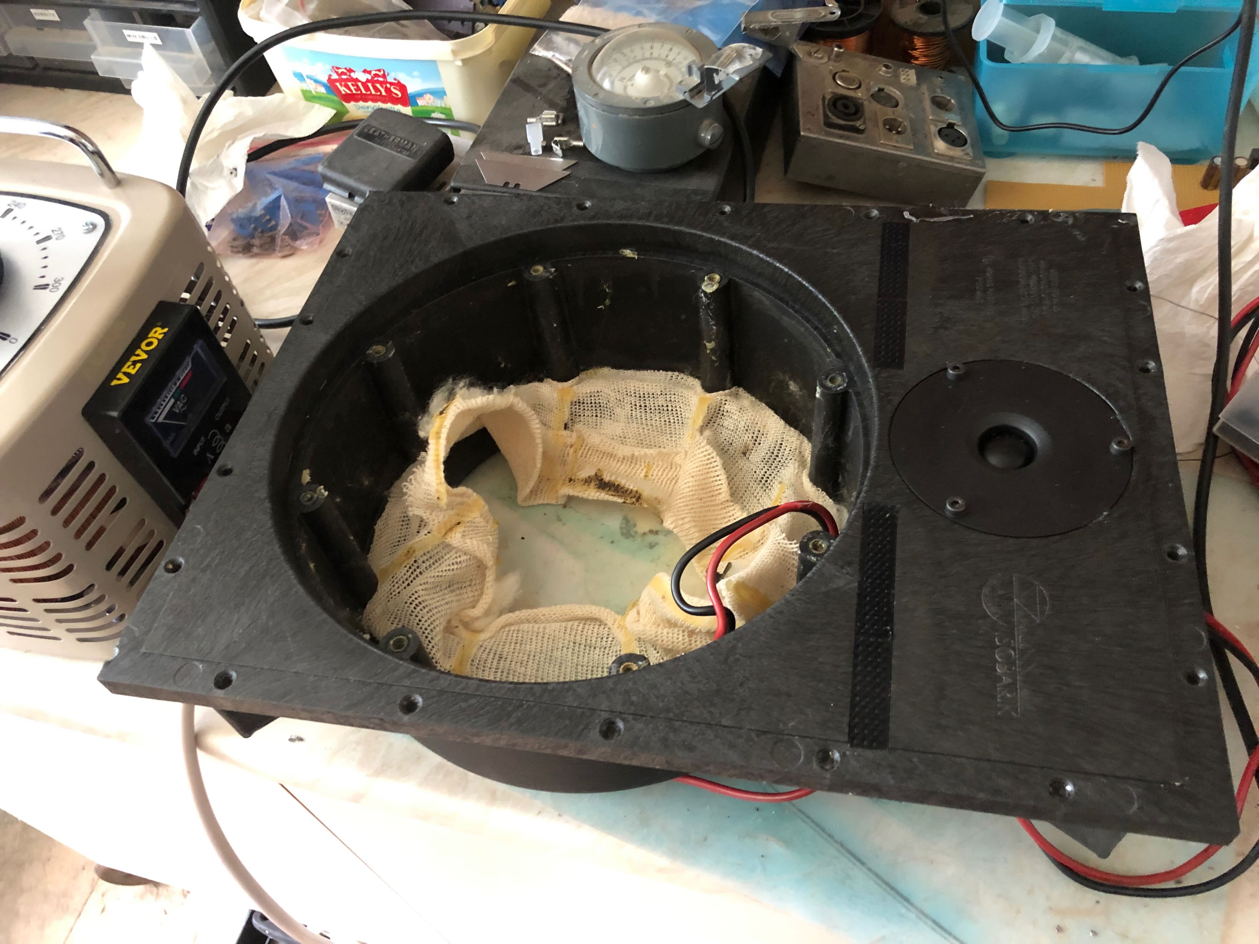
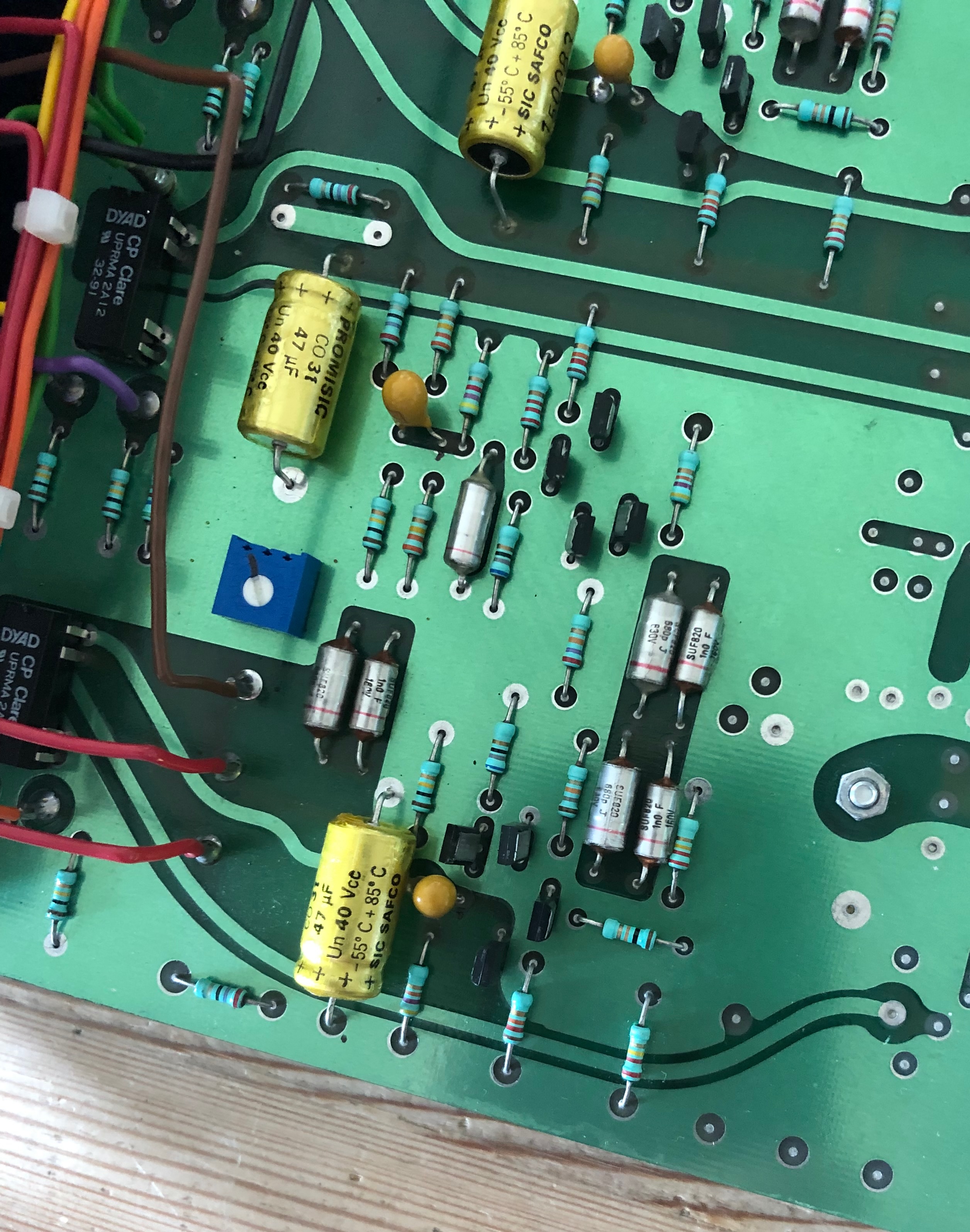
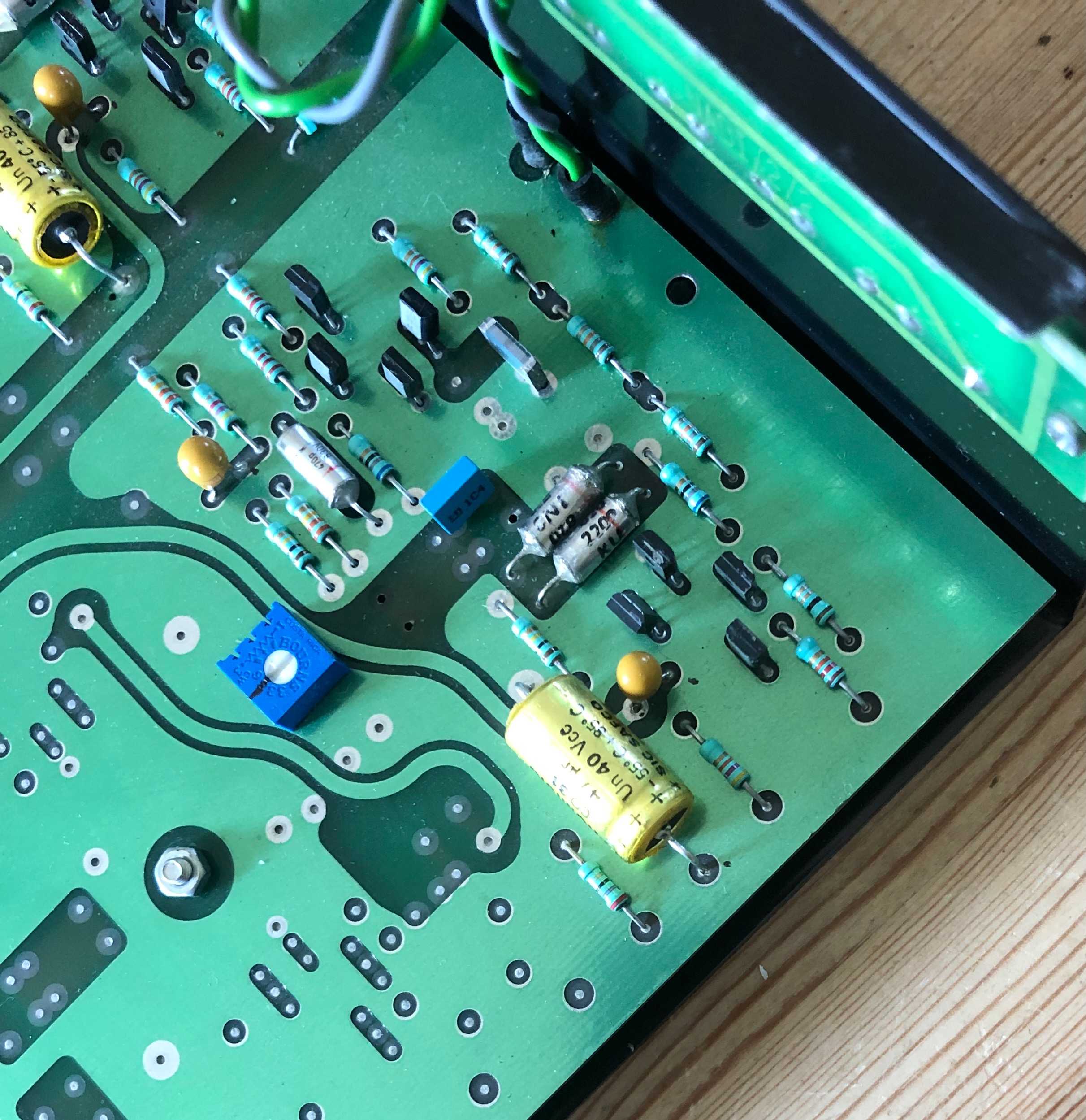
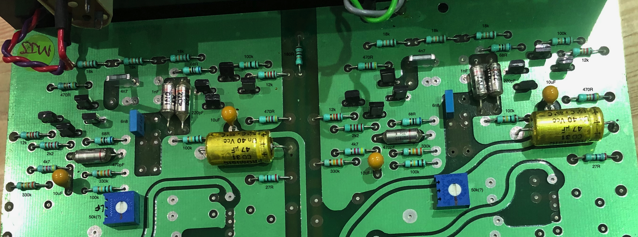
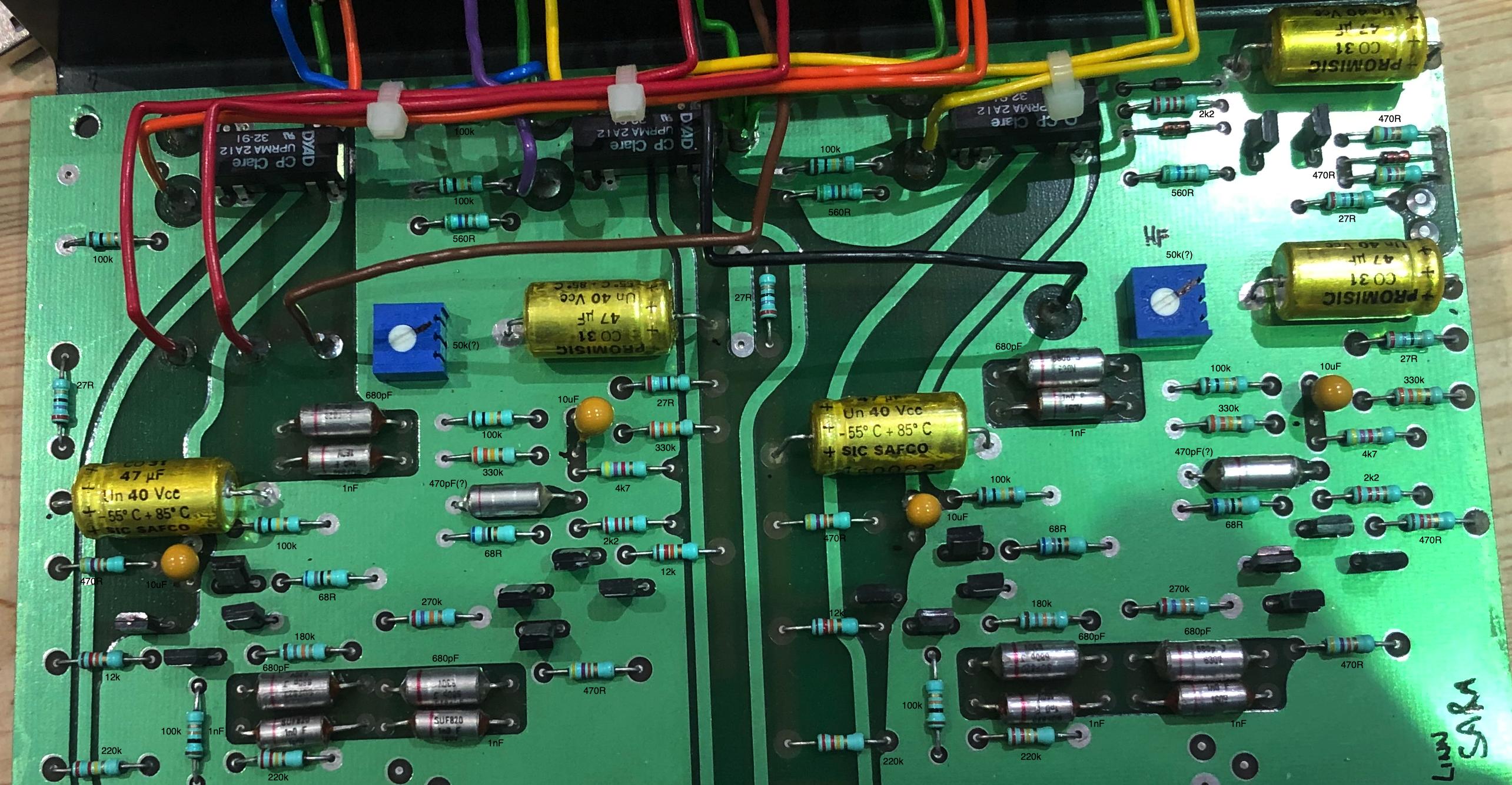
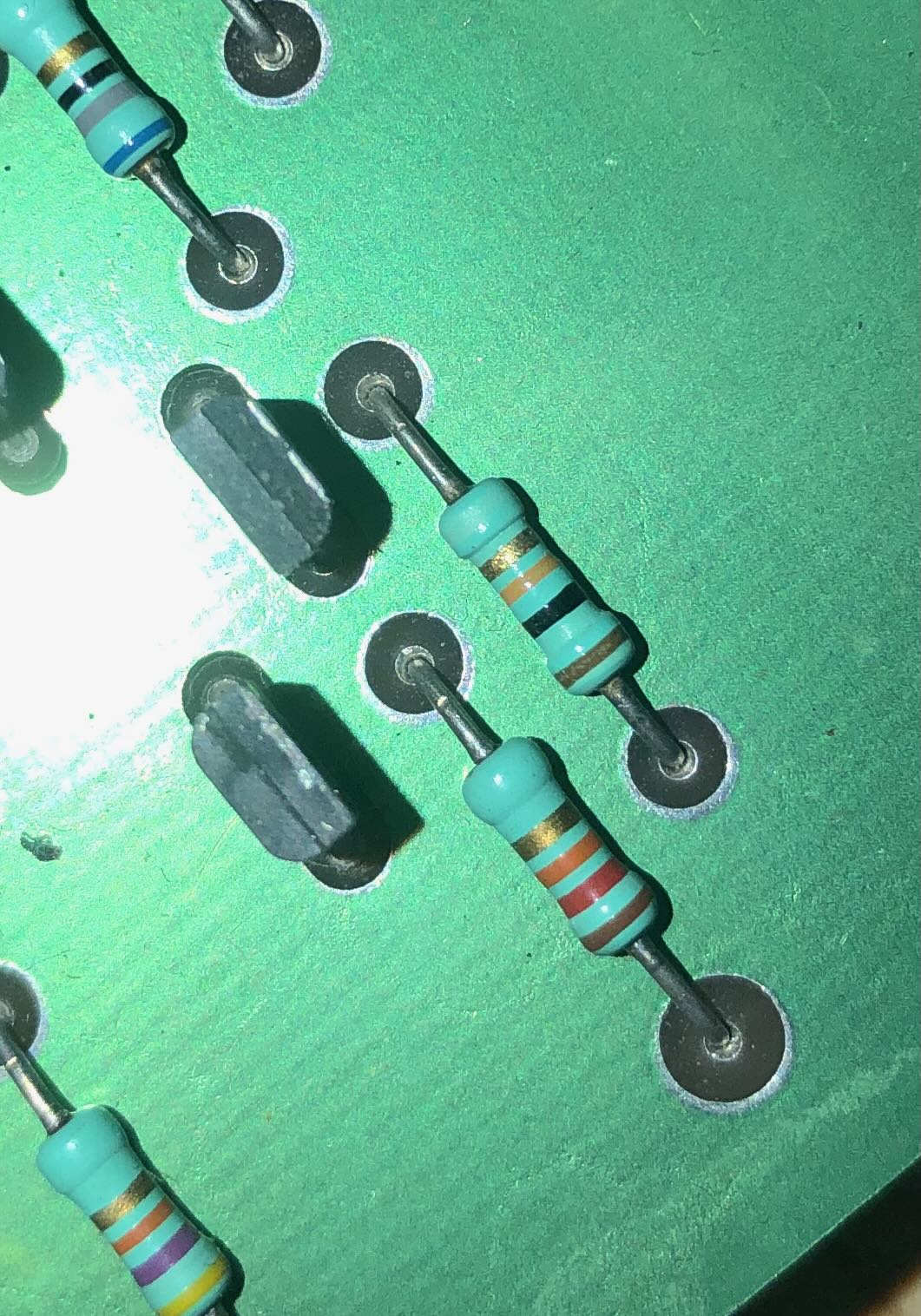
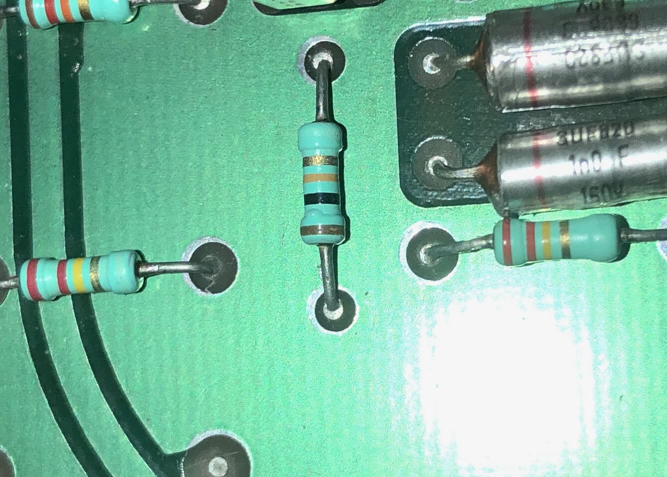
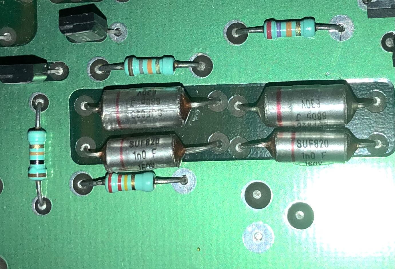
Will try and post pictures for them what might be interested.

Am currently about to stick 2off x 600 x 600mm GIK panels to the ceiling in the Hi-Fi Room if only to get them off the floor.

Still p****d off about my oversight yesterday. At last the one amplifier that I did re-connect properly sounded OK so it was the wrong value LTP emitter resistors causing the distorted output.

Regards

Richard
 
Last edited:
Good Afternoon All,

Wasn't sure whether to post these pictures here or over on the Isobarik thread but as it is related to the ongoing Avondale project......

One Sara9 cabinet with woofer securing ring + one working woofer:-

0nV3KX7.jpg


Wadding from cabinet:-

d7kqUBt.jpg


Wadding from collar between woofers:-

yjotXHW.jpg


One crossover + tie rod and rear connector panel:-

CA7cp0V.jpg


Rear Woofer + tie rod:-

gE3C8z6.jpg


Front panel:-

SezzIB2.jpg


Now just got to wait for the replacement woofer to arrive.

Meanwhile back to work for 4 days tomorrow....

Regards

Richard
 
Bl00dy hell, that's bad news :(.
Been there, done the 'oh, for a moment's extra f'kin thought' thing. Even when impatient now I always make myself walk away, avacuppa andafag and come back with fresh eyes. Cos 10 mins now is worth a lot of swearing, time and possibly money (ESPECIALLY MONEY). My 'chief accountant' operates a very tight ship....:eek::D
 
Good Afternoon All (again),

Well the positive is that the distortion on the SE board is solved. I did a lot of head scratching and then both boards went to laverda who basically replaced all the semiconductors and came back and was still sounding distorted. I have no idea why I thought degeneration resistors would be anywhere near 4k7.

Thought for the day - yes you can buy 0802 sized 47R resistors but you can also buy 2512 sized 47R resistors - one of them is considerably easier to deal with..............

Regards

Richard
 
I used to have big caps in series with diodes across them to block any dc when repairing amps.


Pete
 
Good Afternoon All,

This typed from onboard the Normand Pacific out here on the Naert na Goaithe Windfarm.

Message from Holborn Hi-Fi that the NAXO 2-4 is back from Salisbury so Kate is collecting it as she's heading into Aberdeen this afternoon.

All the pieces are slowly coming together to drive the Sara9's actively with Avondale SE boards.

I just need to be at home..........

Regards

Richard
 
Would be great to pop the lid on the NAXO and have a record of the filter settings for the Sara if you would be so kind Richard. It was a shame none of us had a record of it in the first place!
 
Will,

I should be home on Wednesday. I have several things to be getting on with before heading off to Pikkala in Finland towards the end of the month - I'll have to see if accessing the NAXO will be one of them.

It will be done I'm just not sure when........

Regards

Richard
 
Thanks Richard, and absolutely no rush, just a great opportunity to further collective knowledge for anybody else that wants to give active (the Naim way!) Saras a go. Will be much appreciated when you get the chance and not before! They are keeping you busy :)
 
Good Morning All,

That's me back home and I've taken the lid off the NAXO and taken a couple of photo's. I need to identify which are the critical components for the RC networks:-

PaZGWAt.jpg


bf8cvBP.jpg


Regards

Richard
 
Good Evening All,

I've started having a look at the NAXO schematics as posted on Neil McBride's site and then comparing them with what I see in front of me.

Immediate thoughts:-

1. There is no sign of a variable resistance in NB's schematics
2. The LF circuitry varies somewhat in that there are only one parallel pair of polystyrene capacitors 220pF/ 1000pF. There is a 6n8/ 63V PP type capacitor with nothing in parallel and another single PP type (can't see value). Most resistor values look very similar to Neil's schematic.
3. The HF circuitry seems pretty similar.

I'll take simple overhead photo's and annotate component values as I don't want to dismantle this device at this time.

I'll try not to focus on how much I've been charged to remove 4 capacitors and replace 15.................

Regards

Richard
 
Good Evening All (again),

OK so aided by an iPhone torch, a dentist mirror and blown up pictures I have these images of the NAXO 2-4:-

pdMTS2K.png


Note the Mark Slade signed label!!

b4bO6ij.jpg


Regards

Richard
 
Hi Richard, that is awesome, here is my schematic taken from the McBride and added to.
Yes MJS gets everywhere!
If only my photos were better, I wonder if I still have the originals and can mark them up?

On the HF section you have some resistor values wrong I think, 18k not 180k, 27k not 270k, etc, however it looks a lot like the values I have:

680pF + 1nF, 27k, 680pF + 1nF, 18k, 680pF + 1nF
I was not expecting that?

On the LF section there is a difference, I think you have:

18k, 4n7, 18k, 6n8, 18k, 220pF + 1nF

Where I have:

18k, 470pF + 4n7, 18k, 680pF + 6n8, 18k, 680pF + 680pF
 
Will,

Identify specifically which values you think are wrong and I will double check although I'm pretty certain they are correct as values were checked with their 'mirror' part.

Regards

Richard
 
It is resistor values I think you have read some wrong. I can't see all of the cap values so I am assuming you got those correct!

So looking at the left (of the photo) LF section, near the 180R that feeds the NADI, above a 12k, you have 100k marked that I think it is 10k, I think that third stripe is orange not yellow.

Below that 12k you have a 470R and another 470R over by the 18k top left of the image, but it is hard to see the third stripe colour. My schematic has 47k but are those third stripes orange, or brown, or indeed red? Not always easy to judge! Perhaps my schematic is wrong too!

Same applies to the right (of the photo) LF section.

Looking at the left (of the photo) HF section, I have the same problems, the 100k I think should be 10k is just to the left of the two pairs of 1nF + 680pF. The 470R that may be 4K7 or 47K are mid left just under the 47uF sic safco and bottom right.

Just above the two pairs of 1nF + 680pF you have 180K that I think is 18K and 270K that I think is 27K.

Same applies to the right (of the photo) HF section.
 
Will,

In response to your queries 100k or 10k:-

Ow7bUUt.jpg


The adjacent 12k clearly has an orange stripe, so IMHO the multiplier strip on the adjacent resistor is definitely 'yellow'. 'In circuit' it does measure at 10k.

The resistor I've identified 470R in the bottom left certainly looks like a brown identifier but it measures 'in circuit' at 47k so it could well be orange as it doesn't compare against the brown of the adjacent 12k resistor.

You are also right wrt the is '100k', in comparison to the two adjacent resistors which have a yellow stripe this clearly isn't yellow but faded orange, it measures 10k 'in circuit'.

kgZrhmy.jpg


Again I'd have to agree with your suggestions re both the 18k and 27k as both resistors measure this 'in circuit'.

upk8tD6.jpg


I'm about to re-do my original photographs now........

Regards

Richard


advertisement


Back
Top