
Project stalled for a while, as I was concerned about how to wire in the ALWSR. Seems simple enough, two options in the ALWSR user manual, Super Regulator + Tracking pre-regulator, local sense and Super Regulator + Tracking pre-regulator, remote sense. In general, as I understand it, using local sense avoids some potential instability issues associated with remote sense and is the default option. Well even I could see that using the local sense wiring with multiple ALWSR in the NAXO combined with the NAXO ground plane might lead to troubles:
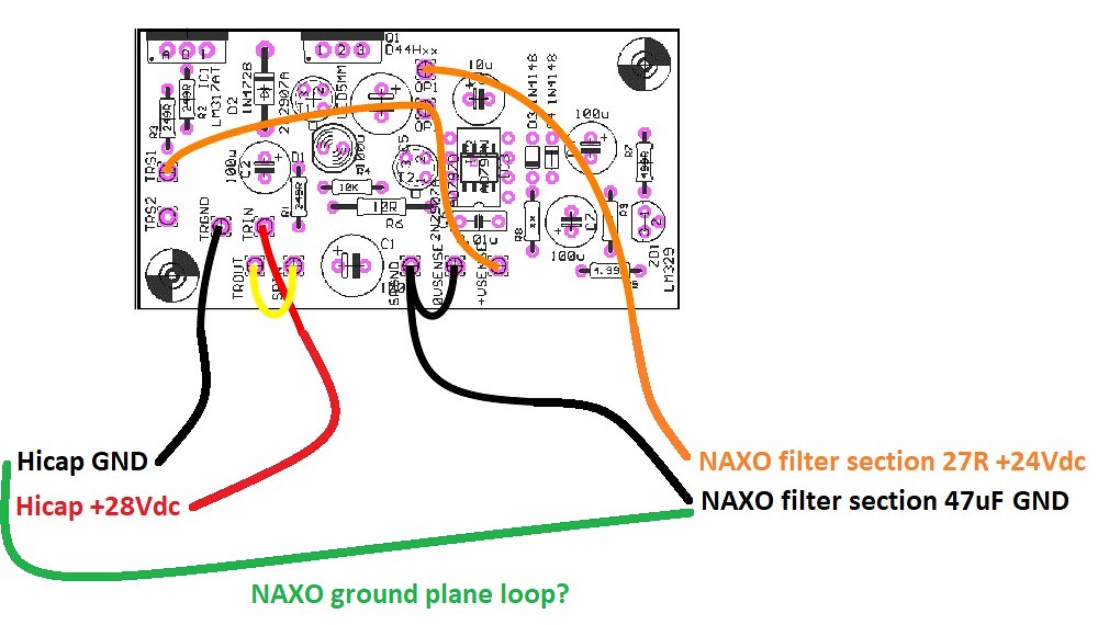 ALWSR local sense NAXO ground loop wiring
So I thought I would go for the remote sense, but somewhat wary of this decision I contacted @Andrew L Weekes. Thanks for your time and patience")
Andrew pointed out two things: I should stick with local sense, but allow the NAXO ground plane to form the sole return path from the load; that the SRGND is the star point ground on the ALWSR PCB so wire in the power to the ALWSR there. So the new wiring scheme is as follows:
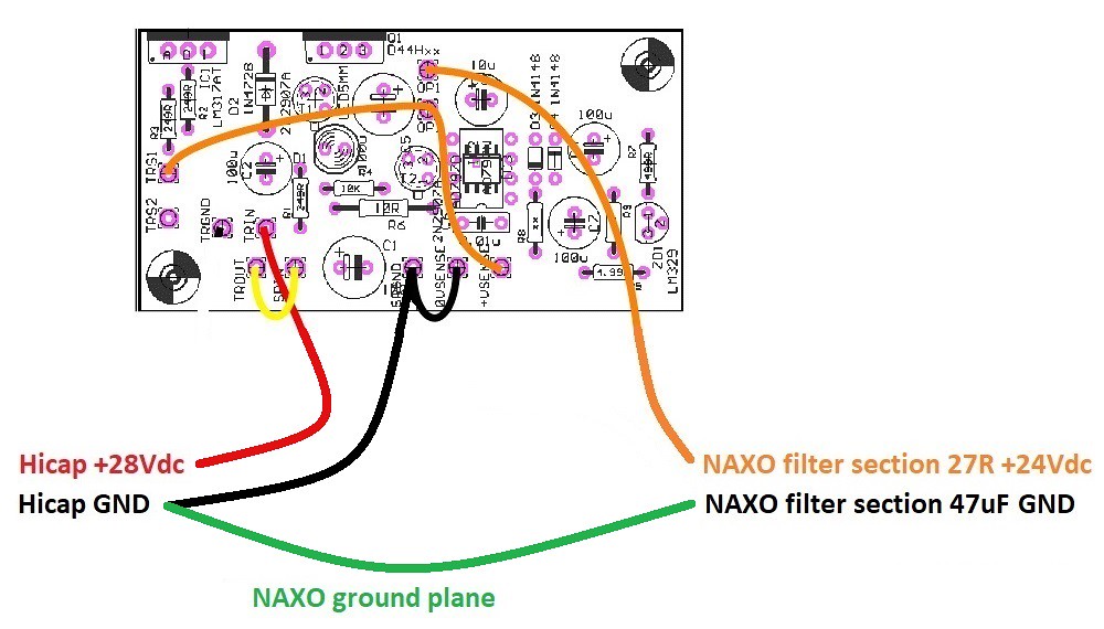 Improved ALWSR local sense NAXO wiring
So next daft question, what size hook up wire?
ALWSR local sense NAXO ground loop wiringSo I thought I would go for the remote sense, but somewhat wary of this decision I contacted @Andrew L Weekes. Thanks for your time and patience
Andrew pointed out two things: I should stick with local sense, but allow the NAXO ground plane to form the sole return path from the load; that the SRGND is the star point ground on the ALWSR PCB so wire in the power to the ALWSR there. So the new wiring scheme is as follows:
Improved ALWSR local sense NAXO wiringSo next daft question, what size hook up wire?
Last edited:
 IMG_20200329_181439458_HDR
 NAXO sweep ch1
 NAXO sweep ch2
 NAXO SBL schematic
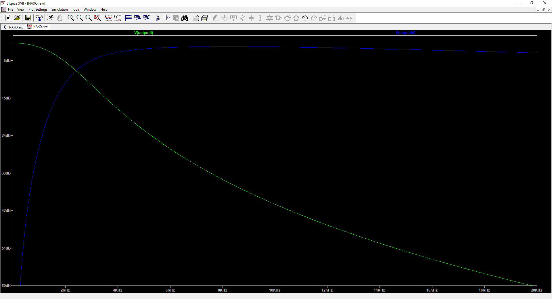 NAXO simulation