
You are using an out of date browser. It may not display this or other websites correctly.
You should upgrade or use an alternative browser.
You should upgrade or use an alternative browser.
Colin Wonfor's SECA amp build
- Thread starter Marra
- Start date
Thanks for the kind words Alan
As Shaun says this amp like the Voyagers is special and well worth building.
Colin will it fit in my listening room
Yes well maybe it will be heavy 50Kgs at least.


And onwards to stage 2
The fan dance
Ive been playing with a pair of these
http://rover.ebay.com/rover/1/710-5...0001&campid=5338728743&icep_item=111880558708
I have them running @7V with those little Maplins Linear PSUs and they are indeed very quiet fanning the sink fins.
Makes a big difference heat wise with the sinks running luke warm rather than hot @ 2.1A which is nice and should allow a little more bias current to be used.
Next step is to find a way of switching them on when the sinks reach 50 deg or so.
Sounding superb
This site contains affiliate links for which pink fish media may be compensated.
PigletsDad
My intelligence test came back negative.
Next step is to find a way of switching them on when the sinks reach 50 deg or so.
Sounding superb
So you want:
1) Something to sense the heatsink temperature.
2) Something to switch the fan voltage on progressively as the temperature rises.
I think a negative temperature coefficient thermistor (say Maplin part FX22Y), and a small power transistor (itself heatsinked for safety) should do the job. Fully turned on, fan needs 160mA, this means you want the base current to the power transistor to be about 2mA when hot, so the sensor resistance needs to drop below 3.5K for full turnon. The suggested part is 15K at room temperature, a 1.2K at 100C, which sounds like the right ball park. Use a small cheap transistor like TIP31C, Maplin part UM82D. You will need to insulate the part from the heatsink. An adjustable resistor (say 2K) would let us trim the turn-on temperature a bit. Any small scrap of metal will do as a heatsink; this only dissipates when partly on, and even then only a few watts. Device is rated at 40W on a big enough sink.
Here is how to connect:
* Fan goes between collector and +7V.
* Thermistor goes between base and +7V.
* Emitter goes to earth.
* Adjustable resistor goes between base and earth. Reducing the value of the adjustable resistor will make it run hotter before the fan starts.
Seems like there are quite a few circuits available.
After a few mins of searching I found these:
http://www.conrad-electronic.co.uk/...onrad-temperature-controlled-DC-fan-regulator
Something a little more DIY
http://electronics-diy.com/electronic_schematic.php?id=1036
Or this
http://www.electroschematics.com/wp-content/uploads/2010/01/Fan-controlled-temperature-circuit.jpg
So you want:
1) Something to sense the heatsink temperature.
2) Something to switch the fan voltage on progressively as the temperature rises.
I think a negative temperature coefficient thermistor (say Maplin part FX22Y), and a small power transistor (itself heatsinked for safety) should do the job. Fully turned on, fan needs 160mA, this means you want the base current to the power transistor to be about 2mA when hot, so the sensor resistance needs to drop below 3.5K for full turnon. The suggested part is 15K at room temperature, a 1.2K at 100C, which sounds like the right ball park. Use a small cheap transistor like TIP31C, Maplin part UM82D. You will need to insulate the part from the heatsink. An adjustable resistor (say 2K) would let us trim the turn-on temperature a bit. Any small scrap of metal will do as a heatsink; this only dissipates when partly on, and even then only a few watts. Device is rated at 40W on a big enough sink.
Here is how to connect:
* Fan goes between collector and +7V.
* Thermistor goes between base and +7V.
* Emitter goes to earth.
* Adjustable resistor goes between base and earth. Reducing the value of the adjustable resistor will make it run hotter before the fan starts.
Thanks PD
That's nice and simple in keeping with the SECA.
I've checked my stock and have some 2K multi-turn Trimmers and my local Maplins actually has the rest in stock.
So almost good to go.
BTW I still have the open plan chassis (one I have the complete amp I'll do the Chassis) so measuring the ambient temp may not work so well but I'll nose the thermistor onto the sink.
I'll be reporting back soon.
Thanks again
Like this Keith
http://www.pinkfishmedia.net/forum/showthread.php?t=179305&page=15
Pauls master build.
I have my fans on outriggers but for testing I just stood them next to the sinks and applied voltage. @ 7V they did not move at all.
it's just helping to move the air more efficiently.
Got to say yes to another excess
Hi PD
Well that control circuit that you generously provided works well.
Here is the rough and ready board.
PDs fan control
 [/URL][/IMG]
And the circuit which may be useful to others (picture painting 1000 words and all that)
 [/URL][/IMG]
Cost peanuts to make
I used this to power it with.
http://www.maplin.co.uk/p/velleman-1a-power-supply-solder-kit-ve58n
Interesting that they are still using photos of the older module. The newer one is even more compact. Ive used these little PSU before for all sorts of test projects and they are a good 1.5-35V work horse.
For testing I just hooked up the above PSU @7V and tickled the thermistor with a little heat gun action.
The fan switched on when heat was applied to the thermistor.
You may have noticed that Colin uses a thermistor for his sliding bias arrangement. The SECA is set up with an ambient temp of 20degs and then bias is set for a sink temp of 50eg. So if the sink runs cooler than 50deg the bias is allowed to rise. It works well and Ive noticed that the sound is even better with the sinks running cool.
Ill need to have a think about the best temp setting to get the max out of the above arrangement.
Thanks PD
Its a pleasure to join the long line of people helped by you.
Having a little read round on the computer forums Ive found that two methods seem to be recommended for fitting the thermistor to the CPU sink.
Drill a hole around 2mm larger than the thermistor into the sink and then use:
1) thermal paste
2) Thermally conductive glue
To fit into place.
Personally I prefer the Glue option for a secure bond to the sink.
Have I missed something?
Input from you PC guys welcome.
Well that control circuit that you generously provided works well.
Here is the rough and ready board.
PDs fan control
And the circuit which may be useful to others (picture painting 1000 words and all that)
Cost peanuts to make
I used this to power it with.
http://www.maplin.co.uk/p/velleman-1a-power-supply-solder-kit-ve58n
Interesting that they are still using photos of the older module. The newer one is even more compact. Ive used these little PSU before for all sorts of test projects and they are a good 1.5-35V work horse.
For testing I just hooked up the above PSU @7V and tickled the thermistor with a little heat gun action.
The fan switched on when heat was applied to the thermistor.
You may have noticed that Colin uses a thermistor for his sliding bias arrangement. The SECA is set up with an ambient temp of 20degs and then bias is set for a sink temp of 50eg. So if the sink runs cooler than 50deg the bias is allowed to rise. It works well and Ive noticed that the sound is even better with the sinks running cool.
Ill need to have a think about the best temp setting to get the max out of the above arrangement.
Thanks PD
Its a pleasure to join the long line of people helped by you.
Having a little read round on the computer forums Ive found that two methods seem to be recommended for fitting the thermistor to the CPU sink.
Drill a hole around 2mm larger than the thermistor into the sink and then use:
1) thermal paste
2) Thermally conductive glue
To fit into place.
Personally I prefer the Glue option for a secure bond to the sink.
Have I missed something?
Input from you PC guys welcome.
Hi PD
Well that control circuit that you generously provided works well.
Here is the rough and ready board.
PDs fan control
[/URL][/IMG]
And the circuit which may be useful to others (picture painting 1000 words and all that)
[/URL][/IMG]
Cost peanuts to make
I used this to power it with.
http://www.maplin.co.uk/p/velleman-1a-power-supply-solder-kit-ve58n
Interesting that they are still using photos of the older module. The newer one is even more compact. Ive used these little PSU before for all sorts of test projects and they are a good 1.5-35V work horse.
For testing I just hooked up the above PSU @7V and tickled the thermistor with a little heat gun action.
The fan switched on when heat was applied to the thermistor.
You may have noticed that Colin uses a thermistor for his sliding bias arrangement. The SECA is set up with an ambient temp of 20degs and then bias is set for a sink temp of 50eg. So if the sink runs cooler than 50deg the bias is allowed to rise. It works well and Ive noticed that the sound is even better with the sinks running cool.
Ill need to have a think about the best temp setting to get the max out of the above arrangement.
Thanks PD
Its a pleasure to join the long line of people helped by you.
Having a little read round on the computer forums Ive found that two methods seem to be recommended for fitting the thermistor to the CPU sink.
Drill a hole around 2mm larger than the thermistor into the sink and then use:
1) thermal paste
2) Thermally conductive glue
To fit into place.
Personally I prefer the Glue option for a secure bond to the sink.
Have I missed something?
Input from you PC guys welcome.
Nice and simple I like it, well done.
ALL PD's work.
Along with my average board work. The circuits that I came up with where much more complex and we all get into that head state of ''complex must be better''. But PD came up with something that even I could build and almost anyone else could and it does what it needs to.
And nicely in keeping with the SECA.
KISS works out again.
I remember PD's comments a few pages back about how fans can improve HS efficiency and my U5 now run as if they had doubled in size.
For the chassis I have a plan to mount the fan low enough to blow under the base plate. Then put a scoop underneath to direct the airflow up through the vents.
A little like PD's idea in a sort of reverse stylie.
That fan discussion really helped me to get to grips with the task and do a little lateral thinking.
Cooler heat-sinks have really made the sliding bias pay off big time.
An even bigger sound and better bass.
Keith
For a few mins work and a little expense it may be worth thinking on.
I'll get the thermistors fitted (waiting on some fresh thermal glue) and then bias play time.
My build is un-fancy but allows enough fluidity to add useful features just like the good old days of the chopping board builds.(without the clip leads)
It's been fun so far
Hi Keith
2.5A
So not much more than now but I'm thinking of the hot summer months and cool running.
I need to have a play with the fan settings but it seems to me that with the fans in use almost any bias setting (within the design OP's) could be tried.
I'll try 2.5A and set up with no fan action to find out what the score is should the fans fail.
Then use the fans to take advantage of the extra bias that can be had from cooling the sinks.
I'll fit the thermistors first and see how it goes.
Interesting
Ive been having a little play with the bias setting today and set up as follows:
Ambient room temp 25deg give or take a foot.
Bias 2.5A
Sink temp 60deg
So 35deg above ambient.
Then I switched the fan on blowing non-stop and the settings where as follows after allowing the temp to stabilise.
Ambient room temp 25eg
The bias slowly went up to 2.75A
Heat sink temp 42deg
17deg above ambient.
So possibly going up to 2.5 with the fans I can afford ambient temp of 40deg and still be within safe operating conditions.
The fans are way cheaper than buying a bigger heatsink and do a good job of cheating the specs up a little for better a damping factor.
And if the fans fail at any point then the bias goes down and still keep things reasonably safe so long as the ambient is not greater than 30deg.
The sound since using the fans with increased bias has grown an even bigger pair bass wise and has expanded a little more in size to my ears and in my set up.
Money well spent.
This tiny mod could add up to another 7W to the SECA without a heat increase.


On this drawing I have removed the earth plain so you can see the track to cut and clean. Do not remove the earth plain the track to cut is on the underside.

Here a nice simple mod to the PSU it will now shut down in a more linear way to protect from silly shorts.
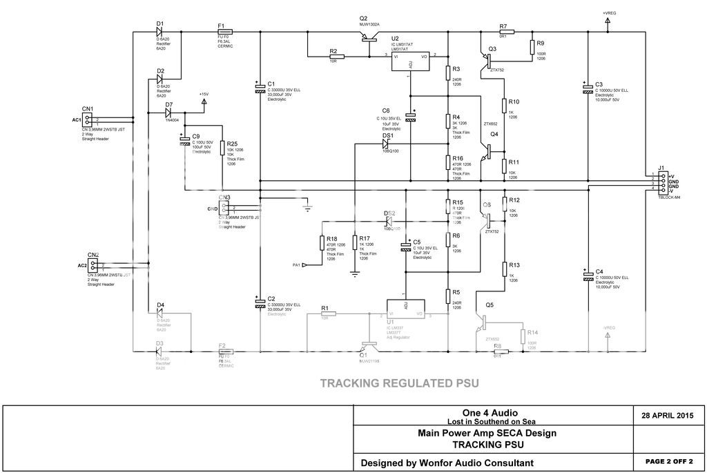
Also I have rearranged the PSU which has with this simple mod will force the PSU board to close down in constant current mode. Less chance of smouldering FET,s
Change R10 to 1K and R11 to 10K, Change R13 to 1K and R10 to 10K as in this circuit.
PSU board with this mod does work and very very well now with this combo it is so close to the £6000. Iridium I doubt if many people could hear the difference, but not as good as James,s Sovereign SECA that is a one of only.
If any body wants to build that you will be looking at about £1000-2000 on parts alone. Ouch said James. And a big electric bill so it only for the rich with there own generators.
On this drawing I have removed the earth plain so you can see the track to cut and clean. Do not remove the earth plain the track to cut is on the underside.
Here a nice simple mod to the PSU it will now shut down in a more linear way to protect from silly shorts.
Also I have rearranged the PSU which has with this simple mod will force the PSU board to close down in constant current mode. Less chance of smouldering FET,s
Change R10 to 1K and R11 to 10K, Change R13 to 1K and R10 to 10K as in this circuit.
PSU board with this mod does work and very very well now with this combo it is so close to the £6000. Iridium I doubt if many people could hear the difference, but not as good as James,s Sovereign SECA that is a one of only.
If any body wants to build that you will be looking at about £1000-2000 on parts alone. Ouch said James. And a big electric bill so it only for the rich with there own generators.
James Evans
Bedroom Bodger
Colin, thanks for sharing this (still haven't finished building mine a year later... so this can be incorporated from the outset).
One question: is the bootstrap mod only applicable if using the tracking PSU?
One question: is the bootstrap mod only applicable if using the tracking PSU?