
Mike P
Trade: Pickwell Audio
A sneak preview of something new I have in the pipeline.
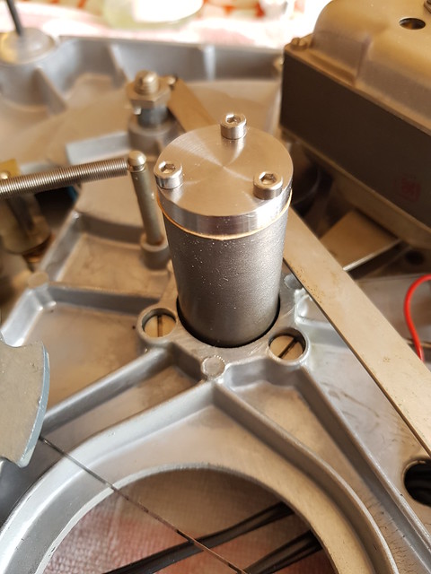 20240327_142436 by Michael Pickwell, on Flickr
20240327_142436 by Michael Pickwell, on Flickr20240327_142436 by Michael Pickwell, on FlickrSchopper usually have original used platters for sale on ebay. I bought mine that way.
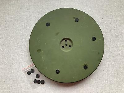
VINTAGE ORIGINAL MAIN PLATTER THORENS TD 124 USED | eBay
We add 6 pcs of new rubber pads (rubber support for top platter). It is NOT the non magnetic platter.www.ebay.co.uk
Wouldn’t this be the setting for 60 Hz rather than 50 Hz, or does it have other functions?The strobe mask (the little black metal plate above the strobe window) needs flipping over.
What bolts have you used to mount the heavy platter to the spindle? If the heads are proud they can interfere as you describe, if level with the recess there should be no issue. Similarly the machine screws that hold the dinked adapter in place need to be right, if they are too long they’ll hit. No issues with the proper Thorens ones, problems only occur is they’ve been replaced at any time with non-standard ones.
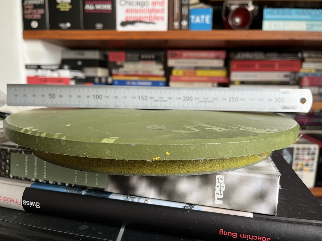
PS This is assuming your light alloy top-platter is flat. Sadly many aren’t. They are very, very fragile.
The strobe mask (the little black metal plate above the strobe window) needs flipping over.
 20240410_202227 by Michael Pickwell, on Flickr
@kevinrt
Have to say, the iron platter seems a lot tricker to install than is often stated here. I see you ran into some problems with yours. Although I’d be curious to try one it’s put me off getting one even more, although as I use an SPU it might not be ideal anyway.
I‘ve had my 124 for over two years now and all seems fine, but do wonder what a good overhaul would deliver.
I have seen an iron platter where the area that sits against the spindle only had a small totally flat portion in the centre and then further out it's was slightly convex. So if you tightened just one screw fully before the others it could pull the platter out of level.
 20240328_194346 by Michael Pickwell, on Flickr