advertisement


Adventures with copper foil cables

awkwardbydesign, that's a little disappointing? not at all awkward! Please consider changing to "accommodatingbydesign" :)

Sure, i see no reason not to use PTFE or similar - i used kapton because I had some, but i do like both the transparency and also the minimal thickness. as you will see shortly, i don't wind in a spiral, though - just one long run along the length - as the tape i use is a little over twice the width of the foil, the excess can be bent to cover the other side of the foil, so one strip of tape fully insulates both sides in one go - i just see this as simpler, neater and quicker to do. It will be better explained in the next episode (i hope)

regarding directionality, i was not trying to indicate that one way was correct and the other wrong - rather just that it sets the live and return in opposing directions, based on the way they came off the spool. My plugs are colour-coded to show which is used for the source (grey plug is source, black plug is receive - this is not the same colour shown in the 3D above but is what i show in the kit pictures), so they always end up being used in the same direction - as you say, i feel its more about burn-in and "aligning the crystals", so that, as you say, they were always consistently run in the same direction as they were during burn-in. I have some background in auditing manufacturing processes, and although i don't know Mundorf in that way, i would be pretty surprised if it was not always the same from them, not because they necessarily think its better, but purely from a manufacturing efficiency perspective, it is easier to set up the line to run consistently the same way

I saw and considered the star line when i was looking at the Eichmanns, and there are certainly some similarities and they look like a good alternative. Because the connectors are rounded, though, they are more suited (in my view) to coax than foils - the Eichmann connectors are flat lugs, with a divider between them, that makes them work nicely with foils, although i see no reason that the Star Line could not work, if you did a little 'shaping' of the foil, to make a better connection to the pin
 
Not sure what episode this is any more, but it’s the one where I give my cables a damn good clean and then mummify them

It’s all Allen Wright’s fault

When I read his cable design book and found that my findings on foil had led to a similar design to his, he was unable to let it rest there, and planted a final nugget that has effectively doubled the build time. It was such a simple phrase: “polish the surfaces to a real mirror finish”

To be fair, when I use a polish (and I tried several, believe me) they all lifted some crud from the surface, even though the cables were new. I have no idea whether this did anything to the sound, but I can certainly see how it does something to the long-term performance – after measuring, cutting etc the cables were all covered in fingerprints (ok, I could have used gloves, I guess), and I can see how over time this may have led to increased tarnish or similar.

Whatever it may have done or not done, they sure looked pretty, as you can see in this before and after image, although the photo does not really do the shininess justice. After trying lots of different copper-specific polishes, I found that an old solvol autosol aluminium polish from the bottom of my bike toolbox was the best of the lot – go figger!
IMG_20230907_215529496 by Simon Kaufman, on Flickr

Now I had it cleaned on both sides, it was time to lock in all the shiny goodness. I lined up the cable and used a few strips of tape to hold it in place, then unrolled a metre of Kapton tape (at 25mm, little over twice the width of the cable), and placed it (carefully) over the cable, then pressed it down, and hey presto, 1 side covered - this is what i show in this photo - you can see the little strips i used to hold the cable in place,
IMG_20230907_220051185 by Simon Kaufman, on Flickr

Now I flipped the cable, revealing the uncovered and still shiny side, and bent over the excess kapton tape on both side onto the now revealed shiny side, locking the cable in fully. I have never managed to do this and give a perfect covering – there are always a few points where the kapton creased a little – but simply running my thumbnail along the length with some pressure got me to a pretty good finish

For the clock-watchers amongst you, I would estimate that cutting each individual cable took 10 mins, and cleaning and Kapton-ing took another 20, so to get to this point took me about 2 hours for all 4 cables needed for a 1m pair

The final picture is the end of the cable, which has either the 20mm or 30mm bare end to act as the connector
IMG_20230907_220520355 by Simon Kaufman, on Flickr

In the next 2 episodes (I promise we are fast approaching the finale) will focus on forming the live & return cables to fit the custom plugs
 
If you are using the Kapton to hold down the foil, is it adhesive?
And as far as my forum name is concerned, my ex SIL called me that once when I disagreed with him (he never liked that; any discussion, he always called arguing). I liked it so much I adopted it, and even had some stickers printed. My local motorbike shop also liked it and wanted to start a club! :D
 
ok - time to connect!

As a refresh, we now have:
  • Directional cable, polished and insulated,with 30mm bare end for the return connection.
  • a plug in 3 parts - not shown is the live insert section,. but in this episode we will make up the return section, and also the cosmetic end cap
IMG_20230908_222537783 by Simon Kaufman, on Flickr

first thing is to insert the bare cable into the plug - as the plug recess is circular, i pre-shape the cable into the same shape - a pencil is close enough to the same diameter - it does not need to be the perfect shape, as it will be pressed further into shape when the live pin is inserted (in a later episode)
IMG_20230908_222743191 by Simon Kaufman, on Flickr

the cable is inserted up to the point of being flush with the top of the plug
IMG_20230908_222948402 by Simon Kaufman, on Flickr
(the plug top is a little rough round the edges, from the surround i used when printing it - only noticed from the photos, but a little work with a file will make it look fine)

now i just secure the cable to the lug using a little masking tape - its surprisingly good at this, and easy to remove if you got it wrong or need to rebuild later
This angle shows the tape clearly, and also the cable now inside the lip of the connector - when the cable is pushed onto the female plug on the kit, this is how the connection is made
IMG_20230908_223124123 by Simon Kaufman, on Flickr

the rest is cosmetic - slide on the outer sleeve and secure onto the same lug, again using masking tape
IMG_20230908_223732260 by Simon Kaufman, on Flickr

and finally slide up the cosmetic cover, so all the masking is covered up, then repeat at the other end, and then you have (drum roll please) half a finished cable!
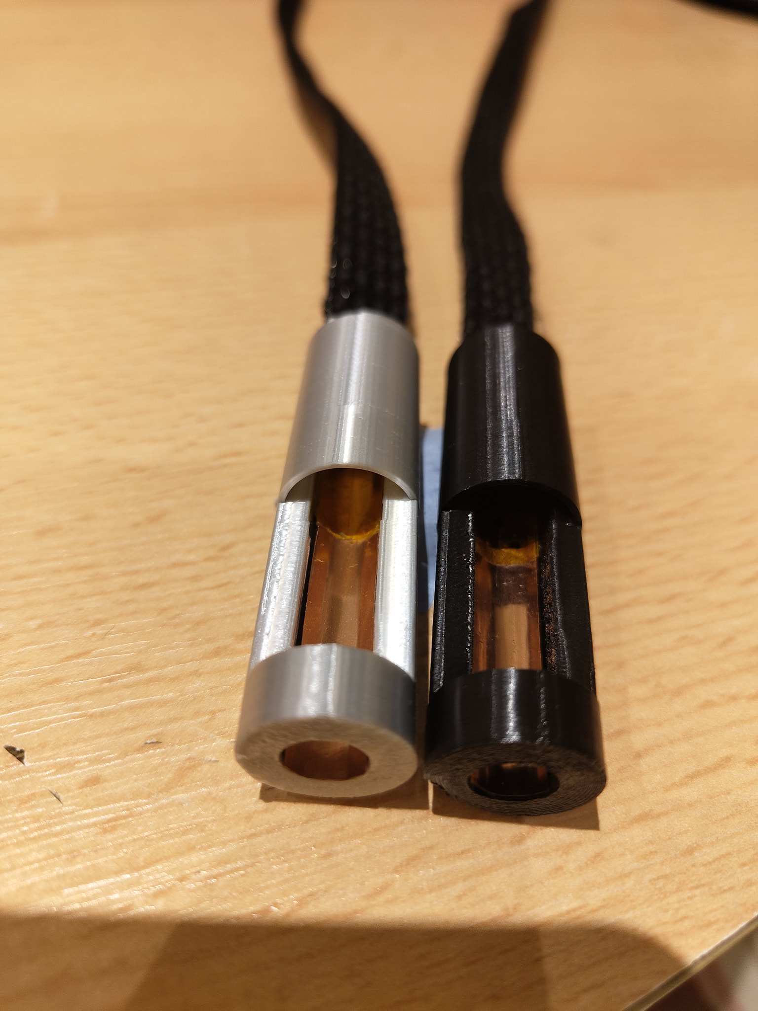
IMG_20230908_224244279 by Simon Kaufman, on Flickr

tomorrow I should complete the build and we can all get on with our lives.....
 
Last edited:
Lives? What lives? This IS my life! Or at least it is when I don't have Covid. :(
I don't have a 3D printer, but I do have a lathe, some Delrin and aly rod.
Was the hex pencil deliberate, or didn't you have a round one? And some dimensions would be useful to me, or a few pics with a ruler.
Oh, and I find that masking tape adhesive hardens over time, becoming very hard to remove.
 
More thoughts. Polishing as fine as possible slows corrosion, I believe, as it has less surface area to get hold of. I have numerous polishes and polishers, and would probably finish with Duraglit wadding. Also I am concerned about the corrosion resistance of unplated copper, so I will probably start by using Star Line RCA plugs, which I already have. Any tips about that would also be useful.
BTW, can you test the capacitance and inductance of these cables? I have meters that will do both, so it will be interesting to compare them with other cables.
 
Was the hex pencil deliberate, or didn't you have a round one?
it's absolutely essential! the sound becomes hard, uninvolving and unbalanced if you use a round pencil. I prefer faber -castell, although Staedtler are a close 2nd - avoid WHSmith own brand. in listening tests, HB was preferred
Sorry- couldn't resist. :)
yes, you are right, the hex shape was on my desk so i used that, but round would have made a bit more sense
 
so I will probably start by using Star Line RCA plugs, which I already have. Any tips about that would also be useful.
i guess it would be as simple as extending the kapton insulation a little further, so there was no possibility of them touching within the plug, and also shaping with something thinner than a pencil, so they were closer to the shape of the lug you were soldering to (i do something similar for my live pin, as will be shown a little later)
to be honest, i do think one of the key benefits of my design is the solderless / direct contact to the female connector aspect, although i do think, in general that foils have much to offer - this is absolutely not a business for me, but i could be persuaded to print some plugs if requested, in return for a £5 donation to a charity, or something like that
 
A few amendments:

1).The combination of outer sleeve + masking tape to retain it was quite thick, and it made it tricky to insert/remove the live pin without it catching. i might make a few spacing changes to the design to make this easier, but there is a simple solution: don't retain the outer sleeve, but rather keep it loose (its fairly "springy" along its length, so as long as the length is correct it naturally wants it extend to the cut length, so does not need any tape to keep it in place, it naturally "wants" to be in that place). This wont work with cotton sleeving, though, which has no inherent rigidity, which is why i might change my design so i have a choice of sleeving
This means that if i do want to dis-assemble , i just slide the sleeving back, remove and then let it go and it spring back to the cut length. When its assembled you would never know its not secured. I also burnt the ends of the sleeving, to fuse them and stop any unravelling

2) I followed awkward's advice, and replaced the masking tape, and just used some tape

3) while I am too modest to follow the suggestion of putting my initials on the plug, i did think that putting the cable width might be a good idea - while i dont have it optimised yet across all my kit, it did seem that not all my boxes prefer the same width (9mm is prefered for phone stage>>pre-amp), so having some identification on the plug seems a good idea for later prints

points 1 & 2 should be visible on the image below. I have also added a ruler for some very rough sizing, as well as an Eichmann plug, for reference - mine are clearly larger, and while i could have made mine shorter, i think the resulting length looks right, considering the barrell is thicker- the proportions just seem pleasing to the eye. in specific terms, they are 60mm long with a diameter of 16.4mm
IMG_20230910_092540838 by Simon Kaufman, on Flickr
 
Thanks for the info Simon. I would be up for 8 black plugs, and a fiver seems a bit low! At least £20 sounds fairer.
I am in the middle of making 4 x 1m XLR leads from solid silver in Teflon, with braided covers (because I already had it all), but usually use Studio Connections RCA leads, again because I have plenty. Plus a couple of Accuphase ASL-10s.
And I can easily drill and tap holes in the plugs for grub screws to clamp the braid, plastic, cotton or silk.
 
Back again ( I have Covid, so you are stuck with me :p). Scaling up*, it looks like your plugs are around 17mm diameter. Is that right? The sockets on my Accuphase are at 18mm centres, so quite tight.
*My KLE plugs are ~ 13mm.
 
Back again (The sockets on my Accuphase are at 18mm centres, so quite tight.
Tell you what - my good friend Andy who runs Winchester hifi, has some accuphase right now (and good choice BTW - very nice sounding kit) so i can try out on his kit in term of spacing - he is away right now and when he get back i am off for a few days, so might be a little while before we can hook up, but it saves printing and sending etc. if they are too tight (but i suspect they will be fine
 
I can easily drill and tap holes in the plugs for grub screws to clamp the braid, plastic, cotton or silk.
Cables are made, and trust me, there is no need for screws to hold the cable in place, unless you end up using cotton - the plugs are designed to have minimal internal clearances, and in the pair i have made, there is zero movement

i have to get a few hours work done, so wont post the full details of the build for a few hours yet - i would say, though, that these are the best design so far, although i am definitely finding a few areas that can be improved
IMG_20230910_124729346 by Simon Kaufman, on Flickr
 
OK folks - for those who have made it this far, well done - its the season finale!

all we have to do now is the live pin and final assembly

pic 1 shows the 2 live pins for 1 cable, and the foil cable ready to be formed. Note that the plastic pin has a central hole, slightly bigger than the live pin needs to be - we will now form the foil to a tube so it can to into this hole
IMG_20230910_100808301 (3) by Simon Kaufman, on Flickr

to form the cable i use a 3mm perspex rod, although it can be any non-metallic rod. its way longer then the round section i need the cable to be, so i just run it along the centre of the foil and wrap about 60mm length around the rod - at this point it does not need not be tight, just roughly formed
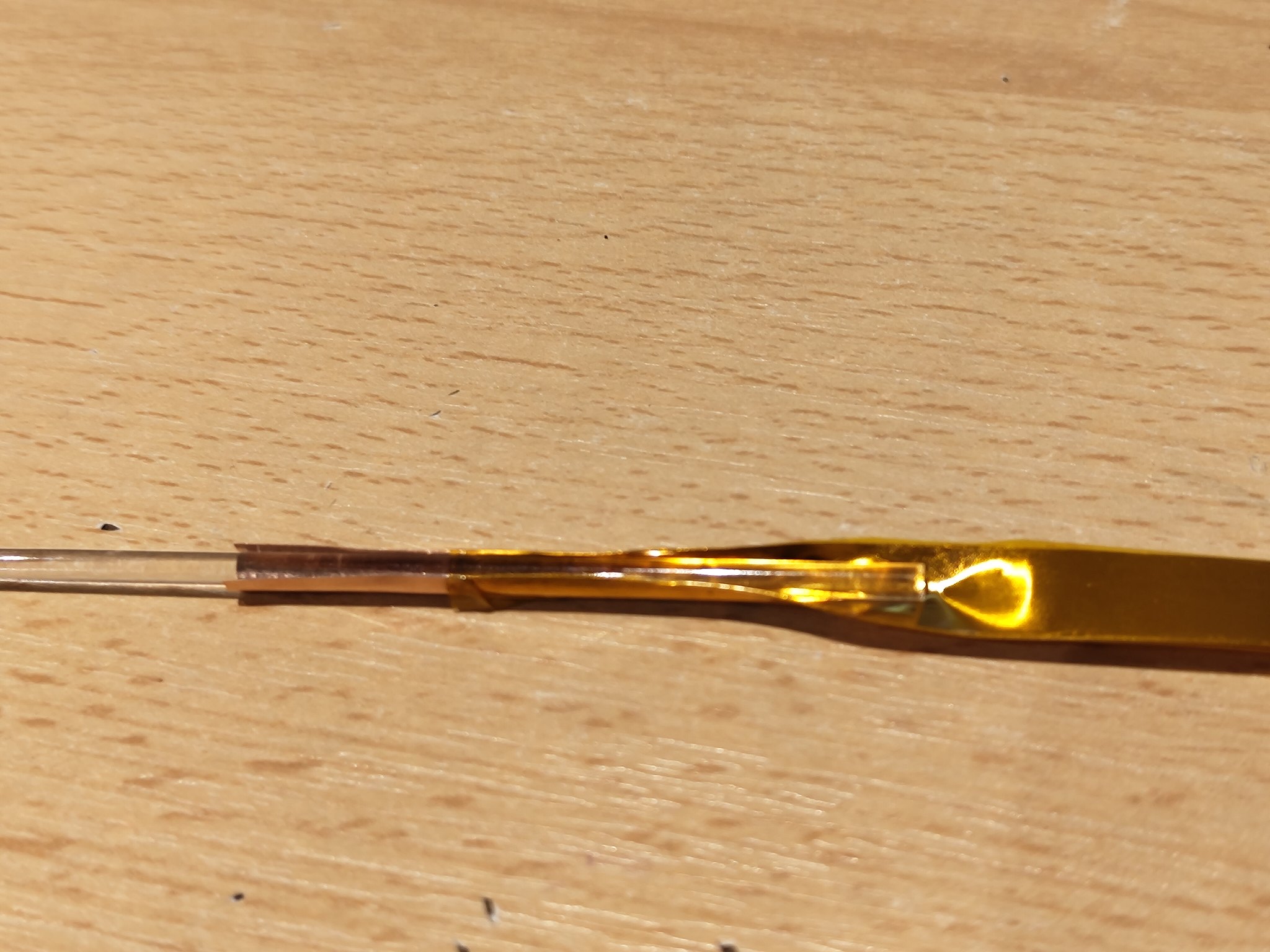
IMG_20230910_101012437 by Simon Kaufman, on Flickr

i then remove the rod (i will need this later) and roll the foil, with very little pressure, until it is pretty circular and reduced enough that it can slide easily through the plastic plug section
IMG_20230910_101108058 by Simon Kaufman, on Flickr


it needs to protrude about 14mm - you can set this perfectly by fitting it at this point and offering it up to the kit (or in my case a female socket from my kit box) and push until it touches the end and will extend no more. At this point you can splay the end so it lays flat against the lug, and then tape it to the lug with a little electrical tape (i didnt take a photo of this but it looks the same, effectively as the earlier one for the return cable
IMG_20230910_101358135 by Simon Kaufman, on Flickr

not simply slide the sleeve over the cable and form the other end, and then slide the cosmetic end caps over the end, and you have 1 finished cable.
IMG_20230910_101412940 by Simon Kaufman, on Flickr repeat the whole thing again and you have a stereo pair (only a single pair is shown)


final point- i said we would reuse the 3mm rod we used when forming the live pin - this is one of my favourite tricks. The formed live pin is rounded to fit inside the female socket, but the size is only roughly rolled and means that although it probably makes some contact its not great. however, if i push the 3mm rod back at this point, AFTER the pin has been inserted, it will slightly expand the copper, making it push hard against the socket, making a really solid contact - in my kit it work really well, to the point that its a little too tight to easily fit with the rod in place, and as you slide it in, you feel some resistance
the picture deliberately shows the rod fully inserted into the copper, but left very long so you can see it clearly poking out the back of the plug in use this will of course be trimmed back
IMG_20230910_124729346 by Simon Kaufman, on Flickr

So that's it - series 1 is done - i found it helpful to write out my thoughts, and am now working on an updated plug design to resolve some niggles, although i don't think it will have any bearing on the sounds, just how it all fits together

Now its done, lets see what the comments and reaction is like - if there is a general interest, then i can share the other main project i am working on, which is a 3D printed tonearm, with carbon tube arm (but that definitely for another day...)

for those who stayed the course, thanks for sharing the journey
 
Simon,

Thank you for showing us the detailed construction of your interconnects which I find very interesting.

Which 3D printer did you use for the housings?

Barry
 
Which 3D printer did you use for the housings?

Barry

Nothing special - its an anycubic Kobra, a little under £200
After a month or so I got very close to spending much more, but although the pricier machines are way faster and more versatile, the basic print quality was not radically better, so I just decided to strip and rebuild the Kobra, and calibrate it to within an inch of its life, and was getting quite passable prints
Still tempted by a hi-end machine such as a bambuLab carbon x1 , but not sure i can justify it - what i enjoyed the most was making my own 3D designs, so a better printer would not affect that
 
The cables made during this thread are in place and nicely working - however, although they work functionally, i was not happy with a few points:
  • inserting the 3mm rod to the live pin was awkward, being difficult to locate the hole it needs to be inserted into
  • the cosmetic cover for the cable exit was not robust - the walls of 0.8mm would not last well, which is fine for me as i can print new ones easily, but not so great for anyone else (again, thiS is not a business, but there is some interest in me making a set for ABD
  • Consider some grub screws to hold the sleeving in place
so back to the drawing board. i redesigned the whole plug, focusing on the cometic end cover
IMG_20230912_161308735 by Simon Kaufman, on Flickr

it was thicker (1.2mm) and also had a central strengthening section that doubles as a locator for the 3mm rod, with the cable lugs sited between the middle section and the outer wall, with enough clearance for a "friction fit" with the sleeving
IMG_20230912_161320256 by Simon Kaufman, on Flickr

with the cable inserted it is now (i think) far more professional looking and functional/easier to use
IMG_20230912_161646805 by Simon Kaufman, on Flickr

but its still not quite enough. the space for the sleeved cable is a bit tight, and the lugs are quite thin and i don't think will last well. I am hampered by trying to keep the diameter as small as i can (they remain 16.4mm).
Making them bigger would solve all my issues, but i want to avoid that if I can. Making them square would also give me more space, but would look a little odd - am going to have a play later to see if there are other shapes, and maybe a square body but with rounded slides would give me what i need?
 
Hi Simon,
I have just reread this thread as I am getting nearer to making my own audio cables.
Have you changed your design since your last post?
All the best
Barry


advertisement


Back
Top