
AguycalledSimon
pfm Member
Season 1 Episode 2: Designing an RCA plug.
I am going to concentrate on my efforts using a 3D printer and not the various failed attempts using off-the-shelf parts which were never a perfect fit and so had very little long-term viability
Before I start, I should also say that I am new to 3D printing and also 3D design, starting only this year, so I am certainly not any kind of expert, however, I have really enjoyed learning and also setting up a very cheap printer (£200) – my advice to anyone thinking about 3D printing is, just go for it
OK – Back to RCA plugs. I had a few must-have solutions to incorporate in my design:
1. Variable sizing to accommodate the lack of dimensional consistency for RCA sockets
2. Designed around flat cable from the outset
3. Cable “became” the contact – zero solder
4· Assembled by hand – no screws, and easy to rebuild/reuse, if needed
So lets take those in order. I have tried to explain as best I can in text but below are also a couple of pictures, showing the 3D model. As I make the next set I will document the build and share the info here, to include a lot more detail about cable preparation etc.
1. Variable sizing: For the outside/return of the plug, I liked what Eichmann did, by heating the plastic so it formed into the perfect sizing for the socket you were using, so I shamelessly copied this. For the live pin I wanted to be able to expand the pin once it was inserted, giving a really solid connection. The final episodes of this mini-series will show this using real pictures of a build, but at this point, imagine a rolled tube which has a slightly larger solid tube inserted into it, expanding the rolled tube
2. Flat-cable specific: The main issue with normal plus was the transition from the connection point (not flat) to how the cable exited the plug (flat). As the plugs I tried all expected a circular coax it was not ideal – the Eichmann solution, using 2 prongs, actually worked quite well, and would be a good option for a DIYer not printing their own plugs. In my design, I added internal hidden channels into the design, which effectively formed the incoming flat cable into the shape I wanted for the live & return contacts at the “business” end of the plug
3. Zero solder: the return connection was routed just under the curved surface of the plug, exiting close to where it meets the socket – pushing the cable further through this routing and then folding it back so it “lined” the recess where the female socket made contact worked well. For the live pin, I formed approx. 5cm at the cable end into a tube and then inserted it into the plug, where I had designed a central tube that was a slightly larger diameter – this pushed through and was proud of the plug, acting as the live pin. Although actually this made contact with the socket and was surprisingly robust, the solid tube mentioned above, inserted after the plug was placed in the socket, made it a really solid connection
4. Assembled by hand: what I set out to achieve was a 2-part plug, with 1 part being the live pin and the other the return, with a method for joining them securely to end up working as a single plug. Its easier to just refer you to the following picture, showing the assembled & disassembled model, than to explain in text
So now we have completed the theory - the next episodes (not sure how many they will be, or how long it will take me to write them up) will go into the detail of the build itself
(Hope the images work – first time I have tried to post an image to PF) 3D RCA by Simon Kaufman, on Flickr
I am going to concentrate on my efforts using a 3D printer and not the various failed attempts using off-the-shelf parts which were never a perfect fit and so had very little long-term viability
Before I start, I should also say that I am new to 3D printing and also 3D design, starting only this year, so I am certainly not any kind of expert, however, I have really enjoyed learning and also setting up a very cheap printer (£200) – my advice to anyone thinking about 3D printing is, just go for it
OK – Back to RCA plugs. I had a few must-have solutions to incorporate in my design:
1. Variable sizing to accommodate the lack of dimensional consistency for RCA sockets
2. Designed around flat cable from the outset
3. Cable “became” the contact – zero solder
4· Assembled by hand – no screws, and easy to rebuild/reuse, if needed
So lets take those in order. I have tried to explain as best I can in text but below are also a couple of pictures, showing the 3D model. As I make the next set I will document the build and share the info here, to include a lot more detail about cable preparation etc.
1. Variable sizing: For the outside/return of the plug, I liked what Eichmann did, by heating the plastic so it formed into the perfect sizing for the socket you were using, so I shamelessly copied this. For the live pin I wanted to be able to expand the pin once it was inserted, giving a really solid connection. The final episodes of this mini-series will show this using real pictures of a build, but at this point, imagine a rolled tube which has a slightly larger solid tube inserted into it, expanding the rolled tube
2. Flat-cable specific: The main issue with normal plus was the transition from the connection point (not flat) to how the cable exited the plug (flat). As the plugs I tried all expected a circular coax it was not ideal – the Eichmann solution, using 2 prongs, actually worked quite well, and would be a good option for a DIYer not printing their own plugs. In my design, I added internal hidden channels into the design, which effectively formed the incoming flat cable into the shape I wanted for the live & return contacts at the “business” end of the plug
3. Zero solder: the return connection was routed just under the curved surface of the plug, exiting close to where it meets the socket – pushing the cable further through this routing and then folding it back so it “lined” the recess where the female socket made contact worked well. For the live pin, I formed approx. 5cm at the cable end into a tube and then inserted it into the plug, where I had designed a central tube that was a slightly larger diameter – this pushed through and was proud of the plug, acting as the live pin. Although actually this made contact with the socket and was surprisingly robust, the solid tube mentioned above, inserted after the plug was placed in the socket, made it a really solid connection
4. Assembled by hand: what I set out to achieve was a 2-part plug, with 1 part being the live pin and the other the return, with a method for joining them securely to end up working as a single plug. Its easier to just refer you to the following picture, showing the assembled & disassembled model, than to explain in text
So now we have completed the theory - the next episodes (not sure how many they will be, or how long it will take me to write them up) will go into the detail of the build itself
(Hope the images work – first time I have tried to post an image to PF)
3D RCA by Simon Kaufman, on Flickr 3D RCA 2
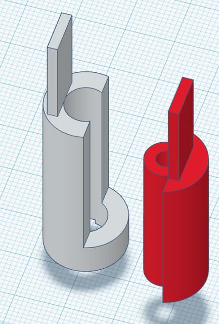 3D RCA
 plugs in situ
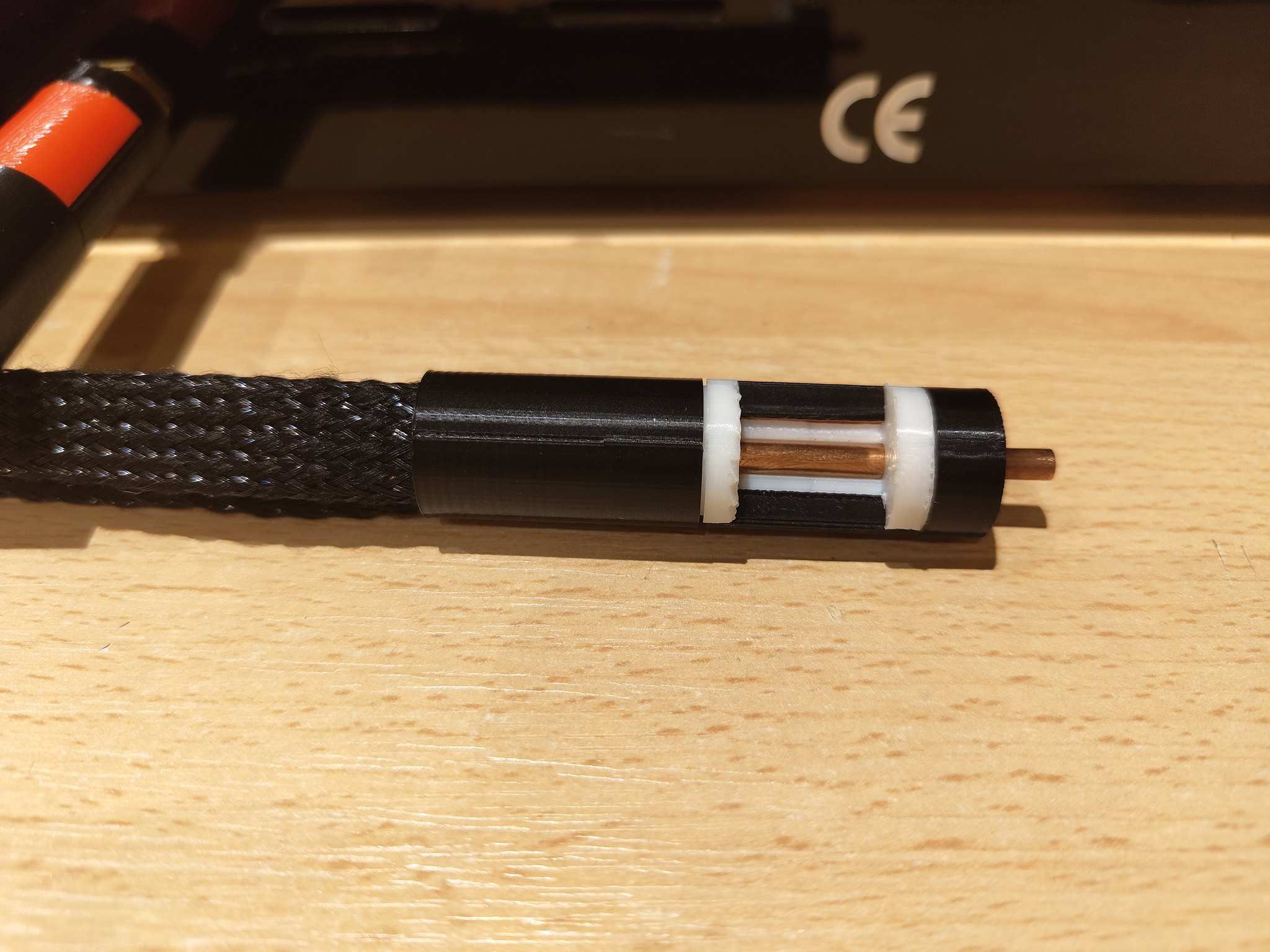 single plug
")
 fig 1 cable length
 fig 2 cable marking
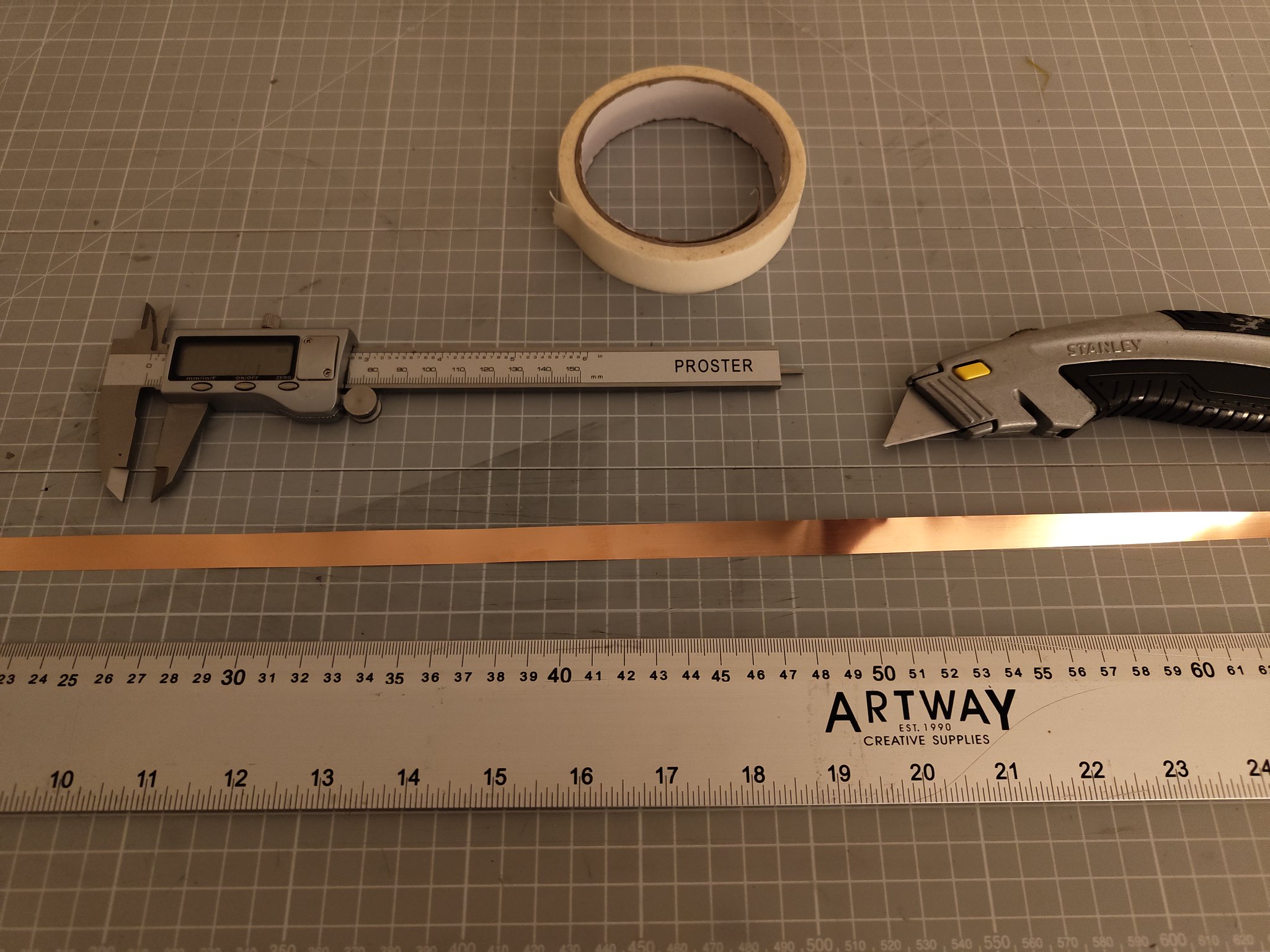 fig 3
fig 3 fig 4
fig 4 fig 5
fig 5 fig 6
fig 6 fig 7
fig 7 IMG_20230906_200455921