
You are using an out of date browser. It may not display this or other websites correctly.
You should upgrade or use an alternative browser.
You should upgrade or use an alternative browser.
Turntable speed analysis part II
- Thread starter flavio81
- Start date
John Channing
fruit box forever
Then i think: How about, for a belt drive turntable, a paddle that sticks out to the side of the platter, said paddle 'rowing' over a pool of viscous fluid? Fluid damping... for the turntable itself !!
In any case it wouldn't be extremely difficult to implement if the paddle is close to the tonearm bearing shaft, and the viscous fluid well is a donut around the bearing...
I had the same thought, a bit like the arm damper used on the Elite/Townsend Rock, but for the platter. Then I realised the simpler solution would be to place a wheel on the other side of the sub-platter opposite the motor which "paddles" through a viscous fluid. Additionally, having this passive wheel means that the forces acting on the platter produce pure rotational torque and the tension in the belt is not pulling the spindle against one side of the bearing liner.
John Channing
fruit box forever
John, when I try the same thing with my Kuzdek it makes two full L_R cycles and returns to its starting position. I load it just short of the point at which the belt slips.
Which is the result I would have been hoping for, your platter drive system is now close to being critically damped
Romy The Cat
Member
the deck I uploaded from is a Micro Seiki SX8000 which has a very substantial platter, I think an air bearing and a dc servo controlled motor with a heavyweight flywheel as far as I know. The quality of the test record is an unknown.
OK, guys I figure out that the Micro test probably from my TT as I give my file to Guy. I do not know the manes of your and I have no idea who run the test. I do not know how to interpret the result that you posted: good or bad you need to explain it to me.
The TT is air-suspended Micro Seiki SX8000 with NO servo controlled motor. It is flat motor with loose belt running the decameter smaller that than platter diameter. The test record is some kind of RAII test record from 50s, old and noisy but it was all that I got at that time. MC needle, End of the Life Phonostage, preamp, line out, Pacific as master mode at 44/16. The file was a bit strange but I did not have time to look more into it. I burned the file running at date, with one try and it was what it was. As the file was playing it was continue homogeneous tone but the file recorded was for some reasons the fluctuation of tone (spikes) that I clearly heard. It looks like the clock was pinging but it shall not be as Pacific own clock is very reliable. I posted as file as I figure that you will discard the spikes. Anyhow, if you fell that my test was faulty then let me know what test record to use and I willing to submit another test after I find why my digital file has the spikes.
Rgs,
Romy the Cat
sq225917
Bit of this, bit of that
Romy, it looks to be a little noisy which we can assume is the data capture and record surface noise, we can discount that from an assessment. It's not perfectly round which means either the record is poorly pressed or there's an issue with the PSU control, belt, bearing etc.
The fact that the errors overlay each other with remarkable accuracy from one revolution of the platter to the next would imply that any error is cyclical in nature and occurs on the record, platter, bearing, as the errors seem to be at perfect multiple of the platter rotation speed.
I have no idea what the 5 spikes are, I'm sure Paul will come up with a suggestion. But discounting all of the above and blaming them on the most likely culprit- the record, I think it's a very good result. The similarities from one revolution to the next are quite remarkable.
@JohnC, Yup, I'm very happy with the way it works. I have another motor to add into the mix to see if that makes any difference at all.
Romy The Cat
Member
Well, I think the explanation of the spikes I have are no way mechanical of cyclical in nature as I do not hear it on record but only on digital copy. The file is located here you can clearly hear the event with open ear:Romy, it looks to be a little noisy which we can assume is the data capture and record surface noise, we can discount that from an assessment. It's not perfectly round which means either the record is poorly pressed or there's an issue with the PSU control, belt, bearing etc.
The fact that the errors overlay each other with remarkable accuracy from one revolution of the platter to the next would imply that any error is cyclical in nature and occurs on the record, platter, bearing, as the errors seem to be at perfect multiple of the platter rotation speed.
I have no idea what the 5 spikes are, I'm sure Paul will come up with a suggestion. But discounting all of the above and blaming them on the most likely culprit- the record, I think it's a very good result. The similarities from one revolution to the next are quite remarkable.
http://www.goodsoundclub.com/jim/
Beside my interest to submit a test file that will not be compromised (and it is something that I would like to do) I keep sinking what might make this noise on digital level. It is remotely possible that the second has some kind UHF noise that in some way interferes with my A/D, creating the spikes and THAT what I would like to investigate as I did not see it before.
Rgs,
Romy The Cat
sq225917
Bit of this, bit of that
Paul, Surely damping any resonance would be good. A shorter decay time for any error, wherever it comes from can only be an improvement?
I'm not saying that I think the improvements come from damping the platter/belt resonance primarily, I actually think it comes from improvements in the motor drive due to the increased load/magnetic effects though I have no way to prove that. If I could test this with thread/tape instead of a rubber belt, to remove belt compliance from the equation, then I would.
I'd love to see the 'bow wave' in the hydraulic reference... ;-)
Paul R
pfm Member
If you want to use the belt as a filter for motor noise then a sharp resonance works best assuming the motor noise is higher than the resonance. I think. The 33/45 data from John's deck suggests the LP12 resonance is too high for 33rpm. It would be really interesting to try a slightly stretchier belt.
Obvious ideas, apply drag directly to the motor rather than via the belt, or a longer belt with a damped tensioning device.
Paul
Obvious ideas, apply drag directly to the motor rather than via the belt, or a longer belt with a damped tensioning device.
Paul
Romy The Cat
Member
OK, I just look into the problem again. I discover that with all my intention to run my Pacific A/D in master mode the Lynx card that interface between my A/D and my PC was set to run from internal clock. So, I fixed the problem and resent Lynx to run from external clock and make Pacific to be a master clock. So, my former test with two separate master clocks has to be discarded.Beside my interest to submit a test file that will not be compromised (and it is something that I would like to do) I keep sinking what might make this noise on digital level. It is remotely possible that the second has some kind UHF noise that in some way interferes with my A/D, creating the spikes and THAT what I would like to investigate as I did not see it before.
I just applauded a new file:
GuyTestNew.wav at http://www.goodsoundclub.com/jim/NewFile
This one with proper digital conversion and it has no auditable spikes. This is a first cut in Cardas test disk. Please do you analyses of the file and explain to me what result you see as I do not understand the diagrams you posted.
Rgs, Romy the Cat
Paul R
pfm Member
Romy take 2,
Demodulated spectrum,

Polar,

This tone is at 1kHz. There is a significant buzz behind it, the spectrum of the recording shows some 60Hz and larger 120Hz and some harmonics.
The process bandpass filters the signal about the carrier, it then FM demodulates it. This gives a signal that represents the frequency of the signal against time, which should be directly related to the platter speed. The first picture is part of the spectrum of that demodulated signal. The second is the demodulated signal converted to polar coordinates with 360 degrees equivalent to one revolution of the platter.
These plots are interesting. The regular waviness in the polar could be either a direct drive signature from the cutting lathe, I think we've not seen this test record before, or it could be a consequence of the motor turning at a whole ratio of the platter speed nd a slight pully eccentricity, or something else altogether.
Paul
Demodulated spectrum,
Polar,
This tone is at 1kHz. There is a significant buzz behind it, the spectrum of the recording shows some 60Hz and larger 120Hz and some harmonics.
The process bandpass filters the signal about the carrier, it then FM demodulates it. This gives a signal that represents the frequency of the signal against time, which should be directly related to the platter speed. The first picture is part of the spectrum of that demodulated signal. The second is the demodulated signal converted to polar coordinates with 360 degrees equivalent to one revolution of the platter.
These plots are interesting. The regular waviness in the polar could be either a direct drive signature from the cutting lathe, I think we've not seen this test record before, or it could be a consequence of the motor turning at a whole ratio of the platter speed nd a slight pully eccentricity, or something else altogether.
Paul
John Channing
fruit box forever
Why would critical damping of the belt/platter resonance be a good idea?
Paul
It might be a good idea. As with a lot of things on a turntable, you have numerous contradictions that need to be balanced. The belt needs to act as a filter, but it also needs to make the platter go round at exactly the right speed. It therefore needs to couple strongly to the motor when it is going at the right speed and decouple from it when it is not. Applying critical damping does not stop the belt acting as a filter, but it does bring things back under control as quickly as possible. Intuitively it feels right (but that is just a guess).
Paul R
pfm Member
Of course.As with a lot of things on a turntable, you have numerous contradictions that need to be balanced.
That's why it's fun to think about it and ask questions.
My thoughts/guesses on adding drag to the platter of an LP12 style TT were that loading a synchronous motor driven with sine waves made it smoother, that the slight belt stretching that happens is somehow a good thing and that the drag smothers the variable load coming from the stylus.
I wonder how much of a simplification treating the belt/platter as a resonant system is, the motor has a modest mass and a substantial electrical 'elasticity'. It might be interesting to add some dragginess at the motor spindle. Or some inertia.
Paul
Werner
pfm Member
I wonder how much of a simplification treating the belt/platter as a resonant system is, the motor has a modest mass and a substantial electrical 'elasticity'. It might be interesting to add some dragginess at the motor spindle. Or some inertia.
Years ago I had a fairly detailed model of DC motor/belt/platter drive. I think it was damn accurate, with one exception: it was very hard to know the damping of the system. The bearing was OKish, you could spin the platter and time its slowdown. But the inherent damping in the belt?
What I found was that drives like this are very resonant (assuming little belt damping) and thus that enormous amounts of drag have to be added to the bearing in order to have any effect. That's why the Hydraulic through or an eddy current brake are potentially much more fruitful ideas.
Drag or inertia at the motor are pointless. Well, that's what the model said.
What was YNWAN's mod, exactly?
That's why it's fun to think about it and ask questions.
I can tell you it cost me so many sleepless nights that it was not funny anymore. I turned my back to it, started a renovation project, and when finished just want to sit down and play music.
OK. I admit. I may try a through or brake.
sq225917
Bit of this, bit of that
Werner, you were looking at a DC motor though, we're talking about an AC sync motor that doesn't droop in relation to load, a different fish entirely- surely?
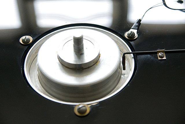
The bearing mod increases drag by replacing the oil with a much higher viscosity fluid such that the spin down time form 33rpm without the belt attached is in the order of 10 seconds as opposed to five minutes.
The bearing mod increases drag by replacing the oil with a much higher viscosity fluid such that the spin down time form 33rpm without the belt attached is in the order of 10 seconds as opposed to five minutes.
pure sound
Trade: manufacturer/distributor
Werner
pfm Member
Werner, you were looking at a DC motor though, we're talking about an AC sync motor that doesn't droop in relation to load, a different fish entirely- surely?
Entirely? No, I don't think so. The model indicated that the motor dynamics play a minor role only.
Mind, the model was created to study higher frequency effects, including dynamic stylus drag, not DC effects and long-term drift. Which is where DC and AC motors differ.
Oh, and it was easy enough to substitute an ideal DC motor, with flat load curve.
In the end the system is almost entirely governed by belt compliance, (unknown) belt damping and/or hysteresis, platter inertia, and platter/bearing damping.
I really should design that brake disk for the Gyro bearing ...