advertisement


Transistor substitutes for vintage Sony amp

Tony L

Administrator
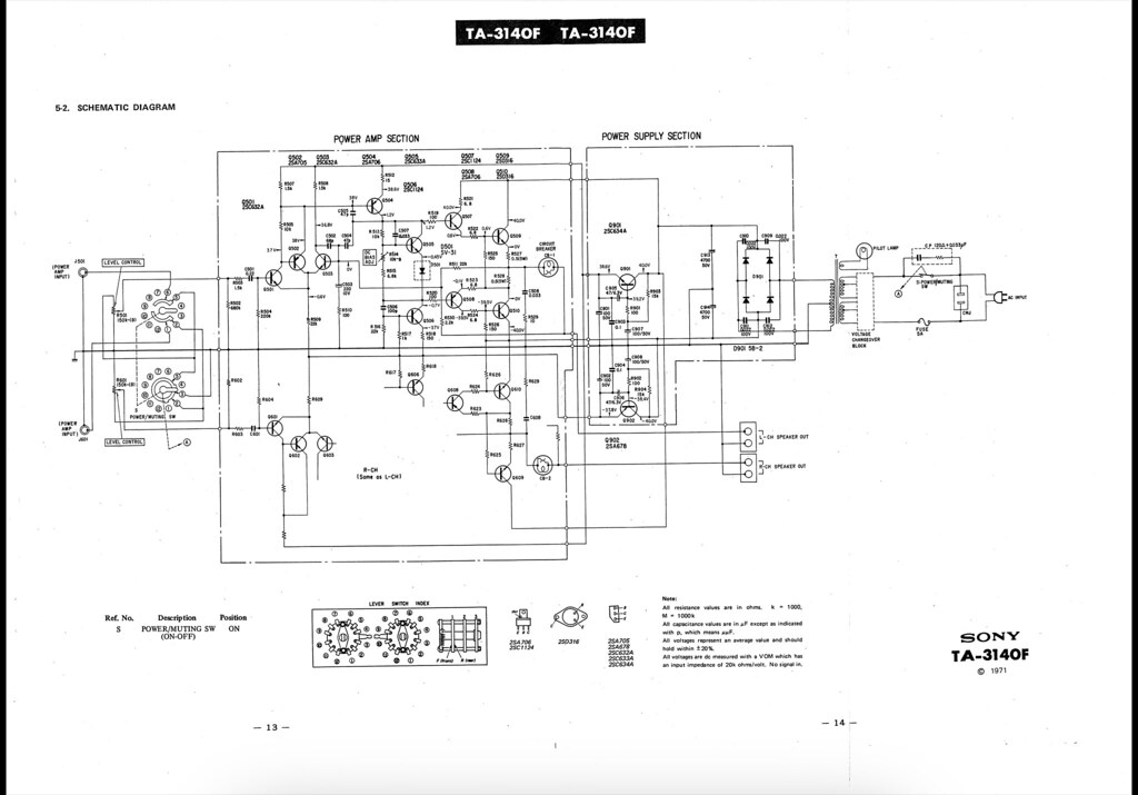
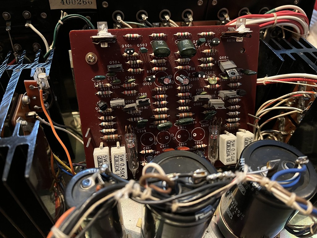
I’m trying to restore a lovely old (1971-74) Sony TA-1140 amp and I’m running into an issue with noisy transistors somewhere. It has a thread in the Classic room, but I don’t think anyone with technical knowledge has read it! The amp works fine, I’ve recapped most of it, but there is intermittent crackling in (I’m pretty certain) the power amp section.

No microphonic issues, tapping the board with a plastic stick reveals no clues. Crackling is on both sides, random, and in stereo, i.e. not PSU which I assume would be mono over both channels. Each channel does its own thing intermittently and it seems to stabilise fully after half an hour or so.

The transistors in the power amp section are as follows:

2SC632A
2SC633A
2SC634A
2SC1124
2SA705
2SA706

Annoyingly they seem obsolete and I’m miles out of my knowledge area here. I’d happily do them all if I could buy them. I don’t understand transistor spec sheets at all. Just totally beyond my education level. I understand enough to grasp that simply finding a “substitute” on a website may not mean it is a genuine drop-in replacement (even allowing for a maybe different pin-out). It appears the 2SC63x types are notoriously noisy so ideally I’d just like to start at the top of the list and do the 2SC632As and work down from that. From what I’ve read they may well be the most likely. Anyone know a drop-in replacement? The service manual is on HiFi Engine.

I’d really appreciate some help here as it is potentially a lovely old amp and is otherwise pretty much mint condition.
 
Hi Tony,

I'm not sure if you ever look at xraytonyb on youtube, but I like a lot of his videos. He is a bit long winded, but did a good job, I think, of his video, linked below on how to find substitutions for discontinued transistors, I think he covers the essentials.


Regards,

Good luck!
 
Thanks, I have watched that in the past, and I’ll do so again later, though I just don’t have the education or electronics understanding to be confident in making a choice. I am very neat at soldering, very good skills there, I could likely get a job on an electronics assembly line, but I don’t understand what I am doing. I’m an Airfix kit builder. Nothing more. This is why I’ve hit a brick wall hard here. If I could just buy what is on the schematic I could certainly fix this as I’d just start at the end I think the issue is most likely to be (I want to do Q501/601 first) and work on from there being prepared to change every transistor.

Here’s a schematic (actually of the power-amp version, but it is a way better scan, it is the same power-amp board):

53334215186_73e5139610_b.jpg


Higher res here.

This site suggests a BC182 as a 2SC632A substitute: https://www.web-bcs.com/transistor/tc/2sc/2SC632A_sim.php

Would the BC182 be a safe bet in that schematic for Q501/601? I understand the pin-out is different so I’d have to stick it in crooked.
 
Are you sure it is transistors - not old carbon resistors?
I'd look hard at the resistors first: they'll contribute bradband / white noise that will be blatant - whereas duff/ noisy transistors will likely have a 1/f + profile - 'pink to brown noise' range, I'd expect.

@davidsrsb is the person to ask.
 
Are you sure it is transistors - not old carbon resistors?

I know nothing! I’m here to learn. To my uneducated eye they look like carbon film, not carbon comp aside from a couple around the speaker selection switch. I made an uneducated assumption about transistors after reading everything on the whole internet about this series of Sony kit. Some are famously noisy and make people’s ‘top ten worst transistors’ lists, e.g. the 2SC632A. They also look a little tarnished the way some old transistors go with very dark legs.

Here’s a picture of the amp board:

53326529923_676e263f5e_b.jpg


What type of resistors are these? They look like carbon film to me aside from R525/625 and a couple I can’t read the numbers from the pic. I can bin all those easily enough if you think they might be it.

Going back to basics these are the things I do know:

The crackling occurs both via speakers and via the (very good) headphone out.

The crackling is in stereo, i.e. both channels entirely randomly and independently.

The crackling occurs with the preamp disconnected (there is a switch on the back).

I ended up with a mystery resistor on the back of the board paralleling R605. That led me down a rabbit hole as the value was different to the schematic. I noticed that changing that value had a pretty profound effect on DC offset. The 1140 schematic says it should be 15k, as I found it the right channel was paralleled, so 7.5k. I tried removing it and that channel quickly went up to 50mV so I turned it off and tried a 10k resistor as that was the value on the TA-3140F schematic above. That started out at about 25mV and settled at 40mV after an hour or so, so I’ve stuck it back to 7.5k even though that is wrong on both schamatics. That gives 20mV after an hour or so and remains stable. I changed the other channel, which was hovering around 30mV to the 10k on the (I assume slightly later) TA-3140F schematic. That channel is now a nice 6-10mV offset. At this point I was happy to hook it up to the little Spendors in the TV system, where, other than the aforementioned crackling for an hour or so, it is great. It is a really nice old amp.

PS For absolute clarity. I do not understand the schematic. I’m just a Airfix kit builder. I have no clue what the various components are doing. I can just put things where people tell me to with an acceptable degree of accuracy. To be honest I hope it is the resistors as I know I could refresh the whole board without screwing up! That much is within my skillset. It is substituting transistors that scares the crap out of me.
 

Here’s a terrible YouTube video that does capture some crackling. These are very insensitive speakers so it is quite subtle, but it is there. Just a crackle. Certainly not unlike a carbon resistor in a valve amp, so Martin may well be onto something given there are some that look like carbon I’d not actually noticed before on the board.
 
I reckon I can see 5 carbon composite resistors in that photo. The ones which have a parallel sided cylindrical body.

As for transistor substitutes; I'm afraid I'm in the same boat as you.
 
Yes, I hadn’t noticed them initially. I’ll do them first. I’ll check my stash, I may even have some of them.

Is there any reason Sony chose carbon comp there? If I have the right values they’ll almost certainly be carbon film. If not I’ll order some in.

I suspect it is healing itself to some degree too, it only did the crackle thing for a minute or two after giving it a rest for an hour or so when I spun a bit of vinyl in the other room. Absolutely silent right now.
The cheap and cheerful carbon resistors are the ones that are not waisted in the middle. Maybe Sony chose them because they are cheaper for bits of the amp not in the signal path as such. As Martin says they are pretty nasty.
 
Yes, I’ll rule those out before going further. The service manual is great (aside from being a poor quality scan on HiFiEngine), so I now have a basket of all the half Watt carbon comps in at HiFiCollective. Just got to pay my idiot tax again for multiple postage on multiple orders yet again and they’ll turn up on Fri I guess.

PS I could really do with thinking about holding a basic ‘stock level’ of components, i.e. try and figure out the most common resistors and caps and order a load of them to avoid these annoying multiple orders. I am gradually building up a collection of stuff as I always tend to order a few extra in case I make a mistake, but I’ve very seldom actually got what I need.
 
Any reason to suppose failing components are at fault here? Intermittent noise that changes with warm-up suggests dry solder-joints, followed by dried-out electrolytics (which shouldn't be the case here), and then crumbly carbon-comp resistors. Solid state tends to work, or not work, (rare E&OE).

I'd reflash everything on and off the PCBs (low heat, short heat, Pb solder) and see if that improves anything.
 
Are you sure it is transistors - not old carbon resistors?
I'd look hard at the resistors first: they'll contribute bradband / white noise that will be blatant - whereas duff/ noisy transistors will likely have a 1/f + profile - 'pink to brown noise' range, I'd expect.

@davidsrsb is the person to ask.
I have met old transistors crackling, but would start with the carbon composition resistors. These are the true cylinders with silver 10% tolerance band. There is no good reason to use a carbon composition in audio, noisy, very non linear with voltage and unstable. Modern metal films have better power rating at the same size.
 
I’ve got replacements for all the half-watt carbon comp resistors on the way (nice Takman carbon film). Should land Friday. I’ll do all six on the power amp board and see where I end up.

I’ll be interested to measure the old ones as they come out too and see if they have drifted. I’ll certainly keep a very close eye on the bias and DC offset levels etc.
 
PS I could really do with thinking about holding a basic ‘stock level’ of components, i.e. try and figure out the most common resistors and caps and order a load of them to avoid these annoying multiple orders. I am gradually building up a collection of stuff as I always tend to order a few extra in case I make a mistake, but I’ve very seldom actually got what I need.
It's semi-easy to hold a stock of 10% resistors, but the number of required resistors as the tolerance goes DOWN goes UP spectacularly. And if you want to hold a sensible number (say 5-10) of each resistor, you'd end up with a big shelf load!

Caps are worse, since type matters, as does voltage, increasing the product envelope.
 
Modern resistors seem remarkably tightly to tolerance. I’m sufficiently colour blind that I can’t trust myself to read colour bands so I only ever do one resistor type at a time and test with my meter it before sticking it in the board. The vast majority seem within one digit, e.g. a 1.5k measures in the range of 1.49 to 1.51k. Capacitors far less so!
 
I would check any transistors before substituting them; why replace working parts? You can get simple transistor testers (some DVMs have a little socket), or there is a crude and nasty test of basic functionality using a DVM (or AVO!). Measure the resistance in both directions between all three leads. One pair should be fairly high in both directions - this will be the emitter and collector. The resistances between the base (the other lead), and emitter or collector should be strongly asymmetric. Collect your DVM between emitter and collector. Lick your finger tips (told you it was nasty), and touch base and one or other lead. You should see a big drop in resistance for one case, much more than if you touch collector and emitter. If it doesn't work, reverse the polarity of collector and emitter connections.

You have checked that base emitter and base collector diodes are good, and that the device shows gain. The common failure modes tend to be failing short, or open (e.g bond wire) and this test catches those. Obviously won't catch fakes or out of spec parts!

Don't try this on FETs!
 
Given the fact that the crackling subsides after warm-up would certainly indicate a thermally related fault. I have a go at those carbon comp resistors, and then your suspect transistors with a can of circuit chiller spray after it reaches stabilized (non-crackly) operating temperature.
 
Modern resistors seem remarkably tightly to tolerance....... The vast majority seem within one digit, e.g. a 1.5k measures in the range of 1.49 to 1.51k.
I don't believe the old story of bin sorting the production spread for 1% 2% and 5% these days and that would make the 5% types all at the wings of the spread, which just does not match what I find
More likely they get the process stable at roughly 1% and then its a choice of compromises on test time and waste


advertisement


Back
Top