advertisement


Time-aligned-filter query

p.st

pfm Member
I found 2 different time-aligned filters. These filters are in the NAC72 and in the NAC102. The filters differ in various components.

Time-Aligned-Filter.jpg


Time_Aligned_Filter_72_102.jpg


NAC72 NA729 Board:

NAC72_729.jpg


NAC102 time-aligned-filter:

NAC102_Time_Aligned.jpg


Are there sonic differences? Which Filter will sound better?

I am looking for the schematics of the filter in the NAC52 and NAC82. Where can I find these schematics?

The NAC82 time-aligned board:

NAC82_729.jpg


which I found by diyaudio.com is wrong!

Peter
 
I put out a similar question and got little feedback.
http://www.pinkfishmedia.net/forum/showthread.php?t=27533
I don't think the resistor values are too critical when matched to the corresponding capacitors. If I remember correctly I calculated the cut off frequencies and they were both ball park so I wasn't concerned about the differences.
However the 22pf or 220uf C5 (C7 on acoustica schematic) has been mentioned in the starfish design, Jim went for 220pf. You actually haven't mentioned this however.

I built my 729 cards (using a section of the pcb from the acoustica site) using NAC 72 values and its fine. How much difference using the other 102 values makes to the sound I wouldn't like to say. I suspect little, although Jim mentioned a difference when changing the 22pf for a 220pf.

I'd be interested to know whats in the other preamps though.
 
However the 22pf or 220uf C5 (C7 on acoustica schematic) has been mentioned in the starfish design, Jim went for 220pf. You actually haven't mentioned this however.


220pF was all my own cock-up. Tired eyes were to blame!

The correct value was 22pF.
Having 220pF in that position causes the filter roll-off to start just inside the top of the audio band (although this can sound quite nice, particularly with some CD players)

Jim
 
The main reason for this contraption is to disguise the shortcomings in the preceeding stage. Address those problems and you can throw this load of trash into the scrap bin where it rightly belongs......
 
Having 220pF in that position causes the filter roll-off to start just inside the top of the audio band (although this can sound quite nice, particularly with some CD players)

Good call. Playing around with the filter values can be a worthwhile way of taming a bright (or giving some life to a dull) sounding system.

The TA filter is not needed when driving one of Les's power amps (no stability problem), but I still keep mine in circuit as I like the resultant sound better than without the filter. Interestingly, the growing band of NOS DAC users might find that a TA equipped Naim pre is an ideal partner as it presents the DAC with an easy load and a decent active filter to help clean up the ultrasonic garbage a little...

Mr Tibbs
 
Good idea!
Actually I have no problem with killing noise much above the audioband as dead as possible. I'm all for it, in fact, given that - off CD anyway - there's nothing useful up there. It's quite interesting to play with low-pass filtering; chnages quite a long way above 'audio' can be easily heard (e.g. the difference between -3db at 50Khz vs 100Khz+) - which says volumes about how sensitive amplification can be to incoming noise.
 
I'm with lesW on this one.......

I never could quite see the point ....but if your going to keep it I'd replace all the signal pat resistors with a minimum of vishay rn55 ?

the 10uf at either end will be emasculating the signal too ....I go for say paper in oil...[which I particularly like in those positions] even the cheap ex ussr military types are very nice sounding, these can be found on fleabay.

A question ? is it this board that creates the "wall of sound " effect
thats common with much of the older naim gear ?
 
I'd bet it's the lack of this board that makes the "wall of sound," as older Naim gear (anything before a 72) doesn't have this circuit.

I should ask if the 72 was the first to have this filter, or was it the 62? I know the circuit was part of the 52 design, but that pre wasn't released until after the 72 and 62 debuted.

M
 
Hello to all

I have been lurking here for some time (please excuse a longish post) and would like to thank EVERYONE who takes the time to share their knowledge and expertise. You have certainly enlightened and helped me.;)

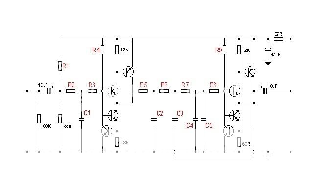
In 2000 I built a 102'ed DIY72 which replaced my DIY42 from 1996. I used a 6 channel 24V DC PSU to power both these pre-amps, with the PSU for the DIY72 being more advanced in that it used LM329CZ voltage references for the LM338K Steel regulators. This PSU definately sounded better than the standard LM338K Steel regulator implementation. Background over!

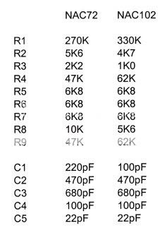
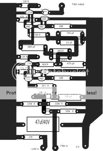
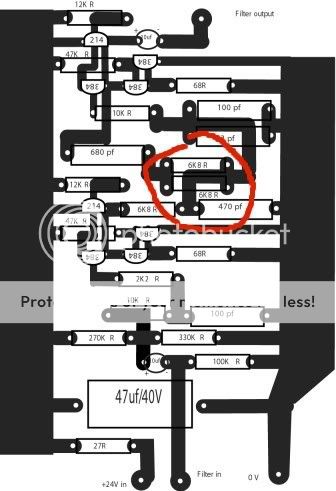
I had also noticed that there were differences in the component values in the buffer/filters stages between different pre-amp models but remained sceptical that there would be any appreciable difference to the sound between them. Late last year I decided to populate a second set of Filter boards for my pre-amp and used the values as shown in the NAC82 layout above. I put them in and with a smug smile of self righteousness, expected to hear no difference at all. The smile vanished from my face as my jaw hit the deck, the improvements were far from subtle.
Improved - low level detail, space, focus, imaging, depth perspective (suddenly spaces between cymbals appeared and one could hear where and how they were being struck), dynamics, timing and a much larger and deeper soundstage to name the most obvious improvements. I hate these hi-fi descriptions as they sound very exaggerated but hope they give some idea of the experience. In short, every aspect of performance is better by an order of magnitude, I am unable to go back to the original cards now.
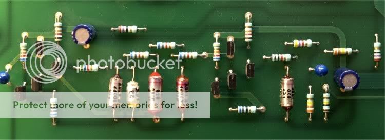
To be fair, I used components from the same batch I bought and used to populate the original cards, to populate the new cards and recapped the old boards. The differences are not due to different or old components!

System context: Linn Sondek LP12/Ittok LVII/Adikt (until Klyde), Naim CDX, DIY72, DIY PSU, DIY135's and rebuilt Dahlquist DQ-10's.

All opinions are mine and results may vary depending on a myriad of factors. Thanks TonyL for a great forum.

Regards
Peter

P.S. From looking at NAC82 pictures the layout presented above seems to be a direct copy of the NAC82 component layout. (Can't check track layout!) Comments anyone?
 
.....just does to illustrate how much detail the original cards lose. Thanks for relating the story PL135.
 
Late last year I decided to populate a second set of Filter boards for my pre-amp and used the values as shown in the NAC82 layout above.

Did I miss something here? The above detailed the difference between the 72 & 102 filter components, which set did you get the improvement with?
 
stevew - the fifth diagram in p.st's original post shows the proposed NAC82 filter/buffer layout found via diyaudio.com. If one looks at the component overlay and the component values, one will notice that some differ to both the 102 and 72 filter/buffer values posted in the second diagram (list).

Taken from diagram five (NAC82):

R1 - 270K
R2 -10K
R3 - 2K2
R4 - 47K
R5 - 6K8
R6 - 6K8
R7 - 6K8
R8 - 10K
R9 - 47K

C1 - 100pF
C2 - 470pF
C3 - 680pF
C4 - 100pF
C5 - 22pF

These values agree with the NAC82 filter/buffer schematic diagram that I have and it is these values that I used in my new boards which wrought the improvements. I was originally using the NAC102 values as per the list.

p.st you are correct, the track layout in the area you have highlighted is incorrect. Componentry and values are correct but the track layout is definitely incorrect.

There is one thing missing from the NAC102 circuit diagram: each unity gain section of the filter/buffer (i.e. before and after the actual filter stage) is powered via it's own 27R resistor and 47uF 35V power filter network. This splits the filter/buffer circuit into two powered sections. For what it's worth my filter/buffer PCB's include this small variation.

Regards
Peter
 
Peter,

if I'm reading your posts correctly, does this mean that the PCB for this bit of the circuit layout of my 102 is the same as that of the 82; and therefore by substituting the components as in your above post, I should get similar improvements?
 
Hi Jo

The filter/buffer circuit of the NAC102 is the same as the NAC82 circuit bar the power supply. There are differences in some component values and physical track layout but in effect you could change a few components and have the NAC82 component values in your NAC102.

What works in my situation may not work to the same effect in yours. All I can suggest is that you try it and see. This is where it gets interesting though, as those who may feel it worthwhile trying the changes, have this forum to share experiences and build a knowledge base. I have certainly learnt a lot from others sharing their experiences.

Regards
Peter
 
Peter,
Thanks... I will try this when I next have the 102 board out of its case. It already has each stage powered directly by Super-regs so the power rail differences between the stock 102 and 82 won't be relevant.

Jo


advertisement


Back
Top