advertisement


There were these amps for sale, and well, I bought them...

What a superb purchase and you’ll really enjoy getting those back on song.

if my eyesight remains in later life I’d love to do the same!!
 
A little progress on one amp, but no pictures of the re-wire yet of the first of a pair.


Today I, re-wired the mains input to the power transformer, heaters wires, HT supply, various grounds, rectifier feeds, speaker output, impedance switch (what fun that is!) and the output transformer. Also, removed the 1964 caps from the PCB, checked the resistor values (all pretty much spot on) and gave the PCB a good scrub.

Inside the cage there is a couple of strips of insulating tape, which I assume is there to stop the cage from shorting out the output transformer or the mains side of the power transformer. Was this a factory fit or an aftermarket, go-faster, inky black mod? :)


I also discovered that the mains selection switch is broken, the pull out and twist bit. It pulls off, rather than pulls out - the little plastic shaft has been snapped in the past. :( I assume I will never find a replacement.

This is a useful place to go for Radford information https://groups.io/g/radford
 
Last edited:
I also discovered that the mains selection switch is broken, the pull out and twist bit. It pulls off, rather than pulls out - the little plastic shaft has been snapped in the past. :( I assume I will never find a replacement.

That could be worse...


Ask Will he may have a replacement. (Or look out on ebay, but there are so may types...)
 
That could be worse...


Ask Will he may have a replacement. (Or look out on ebay, but there are so may types...)

I'm making a list of stuff to ask Will for :). The top nut and bolt of the voltage selector looks very fiddly to re-fit.

I suppose that wire link is at mains voltage?
 
I suppose that wire link is at mains voltage?

It is indeed - not ideal!

You might be able to fix the existing selector by melting a mushroom onto the end with a soldering iron onto the shaft - I have done that on occasion. Although I'd recommend a temp controlled iron and turn it down to something like 150C
 
This is what clinched the deal for me...


SNAP!

Although my boxed up MA15s are Mk2s c/w EZ81 mains rectifiers, they came with a mega rare pre-amp, previous to the scarce Radford DSM pre, built inside a lovely custom chassis.

Possibly just a prototype one off, I have never seen another one like it.

Cannot post pictures cos my stash is packed away in a shipping container since my enforced downsizing, sorry folks. :mad:
 
I'm down with COVID atm so I've had a couple of days to begin re-wiring these amps. The green rot was everywhere especially in the newer of the two amps. It must be storage/usage conditions that bring out the nasty stuff, like this...

PXL_20220728_185247778 by Garf Arf, on Flickr

It gets all over your hands, nasty stuff.

It only troubles the stranded wire, the solid stuff is rot free.

So, some progress. Now I've not polished these and I don't intend to, leave them with the mark of 57 years of age.

A017
PXL_20220729_191517601 by Garf Arf, on Flickr
PXL_20220729_191507761 by Garf Arf, on Flickr
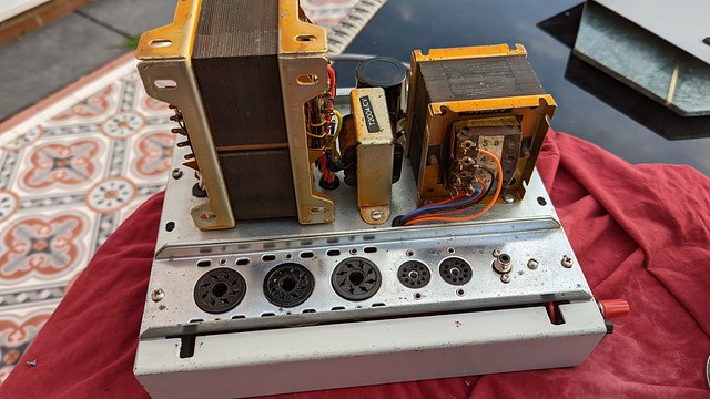
PXL_20220729_191450440 by Garf Arf, on Flickr

The main wiring is complete, but looks messy because the wires to the PCBs are all over the place. These wires will be replaced when I wire in the PCBs.

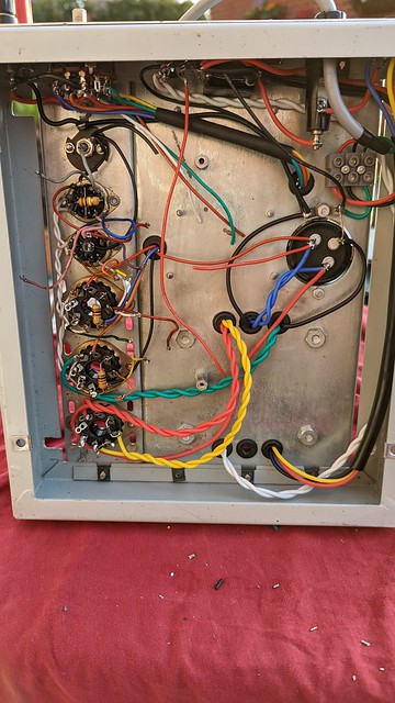
PXL_20220729_185913520
by Garf Arf, on Flickr

A0101
PXL_20220729_185030721 by Garf Arf, on Flickr
PXL_20220729_184924524 by Garf Arf, on Flickr
PXL_20220729_184913163 by Garf Arf, on Flickr
PXL_20220729_184841768 by Garf Arf, on Flickr

PCBs have been cleaned and relieved of their electrolytic capacitors, EL34 cathode resistors replaced with 470R@5W and the anode resistors of the splitter replaced; only one other resistor was out of spec the rest are within spec.

New capacitors are on order. Working myself up to wiring the PCBs in...

Oh and I did the diode protection mod for the rectifier.

PXL_20220729_154737747 by Garf Arf, on Flickr

Most useful tools so far are a glass fibre pen, cotton buds and Isopropyl Alcohol; I've cleaned and scrubbed every connector and eyelet.
 
Spent a couple of hours tidying up the wiring and preparing the PCBs with their hookup wires, just waiting for the capacitors now.

2022-07-31_09-19-26 by Garf Arf, on Flickr

I'm a little dubious of the quality of the flux used in the oldest MA. It is a deep brown and has bubbled over lots of the solder joints. Should I clean it all off or just leave in there?

In fact in the '60s there must have been a solder shortage as whoever built the oldest MA was very stingy with the solder, some of the joints are barely made.
 
Looks like working on it is as interesting as listening to it !
It is very rewarding when it all works.

Previously I built a Statis clone which was a very frustrating build, I had to try four different PSU types, meaning a different amp layout each time, and the bloody thing was so heavy to manhandle.
 
Personally, for such an old and wonderful amp, I would do new soldering by removing most of the old one with an iron taking care not to overheat anything and refill with new solder.
 
Personally, for such an old and wonderful amp, I would do new soldering by removing most of the old one with an iron taking care not to overheat anything and refill with new solder.
I think I will run over the heater connections on the valve bases, taking off the old solder, cleaning the joint and re-soldering.

I've had to rework about 10 of the solder joints on the PCBs as they showed signs of becoming dry; a circular "crack" in the solder. They were mainly around the cathode resistor area, I hadn't noticed them originally.


advertisement


Back
Top