teddy_pardo
Trade: Teddy Pardo
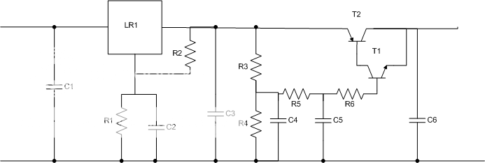
I'd like to share with you the design of a new regulator which as the title suggests is the best regulator I've built so far (including VBE-ed super regulator). There are two alternatives which have a lot in common and both are very good. Like my previous designs, this design is also based on a Gyrator / VBE multiplier (I'll call it VBE) and a linear regulator, but the main change in this design is that the VBE comes *after* the regulator.
R1 = 3.4K
R2 = 150R
R3 = 40-60K
R4 = 330K
R5 = 40-60K
R6 = 100-250R
C1 = 0.1uF X7R Ceramic
C2 = 10-20uF Tantalum
C3 = 10-20uF Tantalum
C4 = 33uF Tantalum
C5 = 0.2-0.3uF X7R Ceramic
C6 = 10-20uF Tantalum/Oscon
T1 = BC547C
T2 = D44H11
LR1 = LM317/LT1086
Motivation:
In previous designs, the motivation to have a VBE before the linear regulator was that the VBE filters all the high frequencies (good line regulation at all frequencies), than the linear regulators assures a low output impedance (good load regulation). The combination of the two was supposed to give the ultimate regulator, and indeed adding a VBE before a super regulator improved the performance very significantly. It also demonstrated that linear regulators, as good as they may be, are not ideal.
A word or two about linear regulators:
Linear regulators have an inherent limitation; they can fix a problem only after it occurs, that is, it can only fix a voltage change after it detects it. In fact it's even worse because in order to fix a problem as fast as possible it over fixes it. When the linear regulator detects a voltage drop it will add voltage to fix the voltage drop until it detects that it added too much and than it starts reducing voltage etc. This process is called overshooting. If this process converges than after a short time the "problem" is fixed, if it doesn't converge we get oscillations
While experimenting with VBEs I noticed that the choice of components is very critical, and by using the right capacitors and transistors the performance improved dramatically. This led me to a hypothesis that having low noise at the output is very important, maybe even more important than having low output impedance. I was also making another hypothesis (based on the above) that even the best linear regulator (ALWSR) makes more noise than the best VBE. I did some tests that easily confirmed my hypothesis, a VBE after the regulator sounds better than before the regulator. But
The output impedance has a non negligible effect on the sound too. A FET based VBE has an output impedance of about 20 ohm and doesn't sound good at all. The effect is an exaggerated mid-bass and a sound with coloration (but still pleasant to the ear). A bipolar VBE has an output impedance which is equal to the sum of R3+R5 divided by the transistor's hfe. With a "home made" Darlington (bc547 + d44h11) I measured (I'll explain later how I measured) an output impedance of about 5 ohm and the sound was just perfect. Better than anything else I've built so far!!!
Output impedance measurements and take two of the design:
In order to measure the output impedance I connected a 200 ohm resistor at the output of the VBE and measured the dropout caused by the resistor. Example: If the output without the resistor is 25V and with the resistor its 24.7V than the added dropout is 0.3V. Since the current is 110mA (25V/220ohm), than the VBE output impedance is 2.7 ohm (0.3V / 0.11A).
Then I added another 200 ohm resistor in parallel and did the measurement and calculation again. It confirmed my suspect that the output impedance varies with the load. The reason is clear and simple, the transistor's hfe varies with the Ic current and directly affects the output impedance. I also made another observation that for a similar reason, the output impedance changes with the transistors' temperature. I looked at the hfe/Ic and hfe/temp graphs in the D44H11 datasheet and found a clear correlation with my measurements. Looking at the D44H11 datasheet I also noticed that its PNP brother, the D45H11 has a much flatter hfe curve, this led me to the idea to try a VBE which uses a PNP Sziklai-pair instead of the NPN Darlington. I tried it and not surprisingly it sounded even better, and measured better too. The output impedance was slightly lower (around 2-3 ohm) and didn't change that much with the current. Now, even in theory, given that Naim is using a 27 ohm resistor in front of the decoupling capacitors, a non variable impedance of 2 ohm shouldn't be an issue.

A note about components:
As stated above, capacitor choice is critical. I've checked a lot of combinations and found that the combination of Tantalum and X7R Ceramic capacitors gives the best results (Polypropylene are almost as good but are large in size and expensive). I know that many people believe that Ceramic capacitors should be avoided in audio (capacitance varies with voltage, microphony, etc), but here they just sound great, try it!
I also tried and measured various transistors with different hfe, including very high hfe transistors, and found that the bc547/d45h11 combination gives the best results.
Implementation:
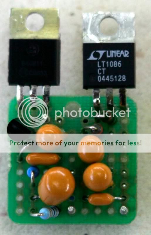
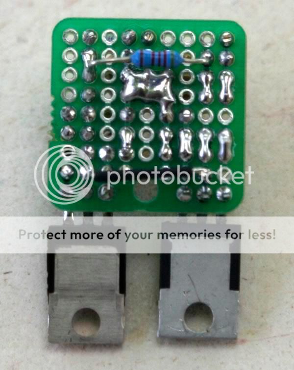
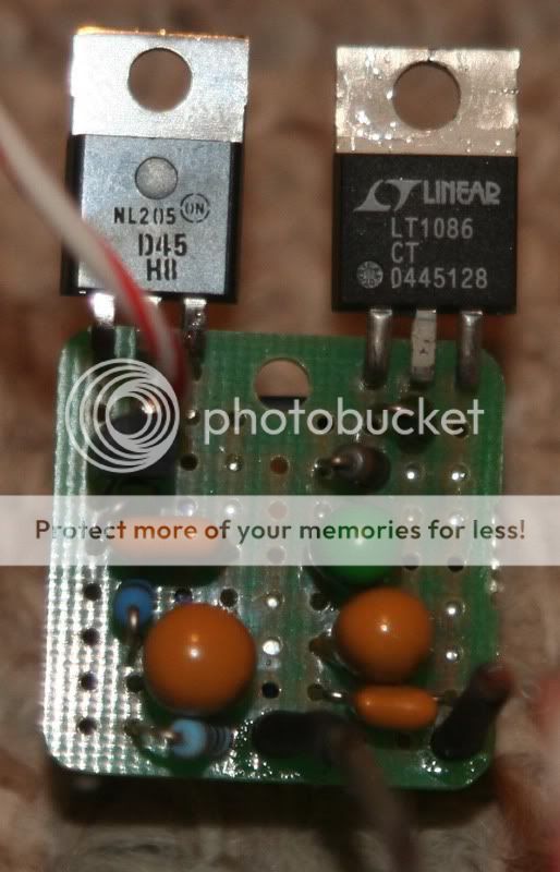
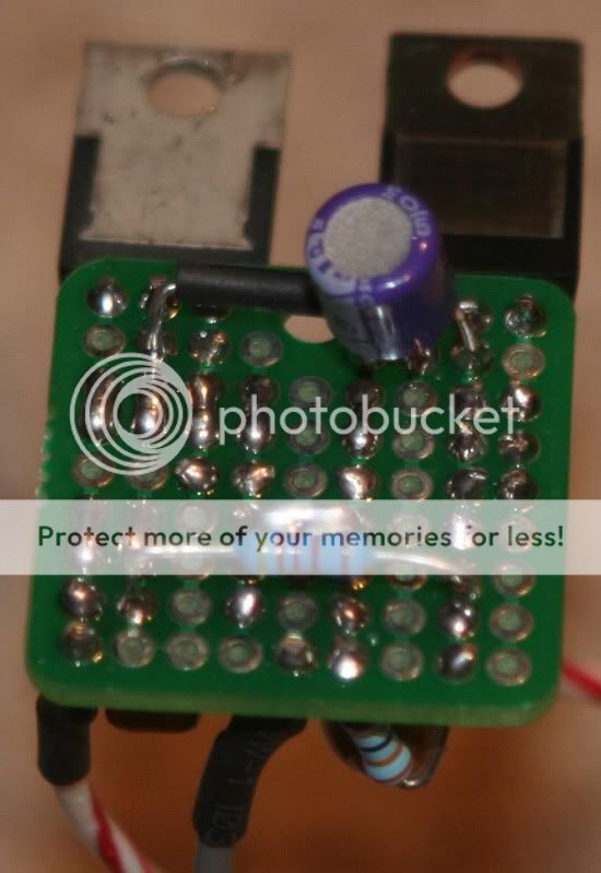
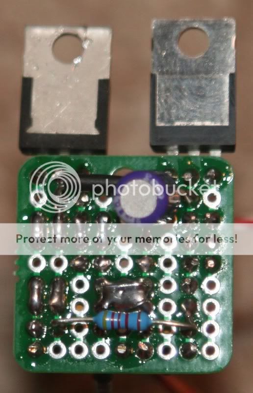
The following pictures show how such a regulator can be built using a 1x1 inch strip board. Note the star ground design
The NPN darlington
The Sziklai-pair
These small strip boards can be found on ebay
Note that the holles on this strip board are conneted by groups of three and I added solder whenever I needed longer strips.
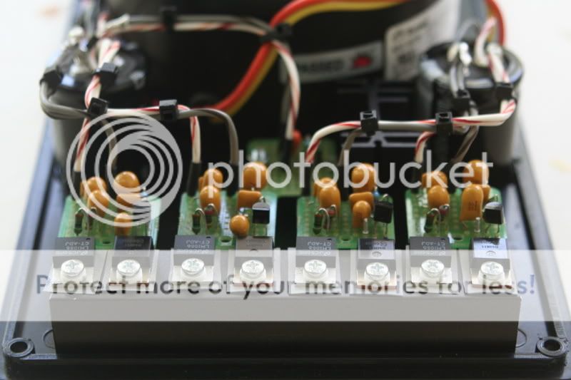
Here are some pictures of an accomplished dual HiCap + napsc compatible PSU built using this regulator. It sounds really good !!!!
Note the use of a heat sink to minimize the temperature effect on the hfe


BTW, I call this regulator a TeddyReg...")
Enjoy, Teddy
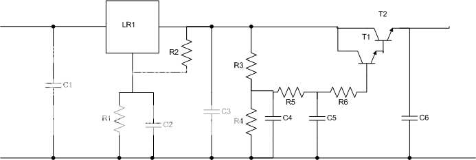
Note: I fixed the Sziklai-pair diagram, it is correct now
R1 = 3.4K
R2 = 150R
R3 = 40-60K
R4 = 330K
R5 = 40-60K
R6 = 100-250R
C1 = 0.1uF X7R Ceramic
C2 = 10-20uF Tantalum
C3 = 10-20uF Tantalum
C4 = 33uF Tantalum
C5 = 0.2-0.3uF X7R Ceramic
C6 = 10-20uF Tantalum/Oscon
T1 = BC547C
T2 = D44H11
LR1 = LM317/LT1086
Motivation:
In previous designs, the motivation to have a VBE before the linear regulator was that the VBE filters all the high frequencies (good line regulation at all frequencies), than the linear regulators assures a low output impedance (good load regulation). The combination of the two was supposed to give the ultimate regulator, and indeed adding a VBE before a super regulator improved the performance very significantly. It also demonstrated that linear regulators, as good as they may be, are not ideal.
A word or two about linear regulators:
Linear regulators have an inherent limitation; they can fix a problem only after it occurs, that is, it can only fix a voltage change after it detects it. In fact it's even worse because in order to fix a problem as fast as possible it over fixes it. When the linear regulator detects a voltage drop it will add voltage to fix the voltage drop until it detects that it added too much and than it starts reducing voltage etc. This process is called overshooting. If this process converges than after a short time the "problem" is fixed, if it doesn't converge we get oscillations
While experimenting with VBEs I noticed that the choice of components is very critical, and by using the right capacitors and transistors the performance improved dramatically. This led me to a hypothesis that having low noise at the output is very important, maybe even more important than having low output impedance. I was also making another hypothesis (based on the above) that even the best linear regulator (ALWSR) makes more noise than the best VBE. I did some tests that easily confirmed my hypothesis, a VBE after the regulator sounds better than before the regulator. But
The output impedance has a non negligible effect on the sound too. A FET based VBE has an output impedance of about 20 ohm and doesn't sound good at all. The effect is an exaggerated mid-bass and a sound with coloration (but still pleasant to the ear). A bipolar VBE has an output impedance which is equal to the sum of R3+R5 divided by the transistor's hfe. With a "home made" Darlington (bc547 + d44h11) I measured (I'll explain later how I measured) an output impedance of about 5 ohm and the sound was just perfect. Better than anything else I've built so far!!!
Output impedance measurements and take two of the design:
In order to measure the output impedance I connected a 200 ohm resistor at the output of the VBE and measured the dropout caused by the resistor. Example: If the output without the resistor is 25V and with the resistor its 24.7V than the added dropout is 0.3V. Since the current is 110mA (25V/220ohm), than the VBE output impedance is 2.7 ohm (0.3V / 0.11A).
Then I added another 200 ohm resistor in parallel and did the measurement and calculation again. It confirmed my suspect that the output impedance varies with the load. The reason is clear and simple, the transistor's hfe varies with the Ic current and directly affects the output impedance. I also made another observation that for a similar reason, the output impedance changes with the transistors' temperature. I looked at the hfe/Ic and hfe/temp graphs in the D44H11 datasheet and found a clear correlation with my measurements. Looking at the D44H11 datasheet I also noticed that its PNP brother, the D45H11 has a much flatter hfe curve, this led me to the idea to try a VBE which uses a PNP Sziklai-pair instead of the NPN Darlington. I tried it and not surprisingly it sounded even better, and measured better too. The output impedance was slightly lower (around 2-3 ohm) and didn't change that much with the current. Now, even in theory, given that Naim is using a 27 ohm resistor in front of the decoupling capacitors, a non variable impedance of 2 ohm shouldn't be an issue.
A note about components:
As stated above, capacitor choice is critical. I've checked a lot of combinations and found that the combination of Tantalum and X7R Ceramic capacitors gives the best results (Polypropylene are almost as good but are large in size and expensive). I know that many people believe that Ceramic capacitors should be avoided in audio (capacitance varies with voltage, microphony, etc), but here they just sound great, try it!
I also tried and measured various transistors with different hfe, including very high hfe transistors, and found that the bc547/d45h11 combination gives the best results.
Implementation:
The following pictures show how such a regulator can be built using a 1x1 inch strip board. Note the star ground design
The NPN darlington
The Sziklai-pair
These small strip boards can be found on ebay
Note that the holles on this strip board are conneted by groups of three and I added solder whenever I needed longer strips.
Here are some pictures of an accomplished dual HiCap + napsc compatible PSU built using this regulator. It sounds really good !!!!
Note the use of a heat sink to minimize the temperature effect on the hfe
BTW, I call this regulator a TeddyReg...
Enjoy, Teddy
Note: I fixed the Sziklai-pair diagram, it is correct now
This site contains affiliate links for which pink fish media may be compensated.