
Mike P
Trade: Pickwell Audio
Its a horrible wet and windy day here in Sheffield so I thought Id take some time to share with you my Sony 337ESD vintage CDP upgrade project.
I wasnt sure whether to put this post in the classic or DIY section or if it should even go in the system pics thread. The moderators can feel free to move it as they see fit.
The 337ESD is a formidable beast dating from the late 80s back when CD was king and the big audio companies were making CD players built like battleships. The Sony 337ESD is one of the top models from Sony at that time and probably only comes second to the even mightier 555ESD.
This player is huge and incredibly solidly built. The pictures dont really convey the scale but its about twice the size of my old Arcam Alpha 5 and probably four times as heavy!
The 337ESD uses my favourite DAC chip, the TDA1541A. Actually, in the 337ESD there are two TDA1541A DACs arranged in what Sony call staggered parallel configuration somehow supposedly giving 18 Bit performance.
The laser mechanism is the simply superb Sony KSS190A which uses linear motor on magnetic rails for tracking rather than the more common nasty plastic gears. The laser head slides on polished steel rails and rests in a cast aluminium baseplate. The spindle motor is a brushless hall effect item and has a beautifully machined all metal clamp. In fact pretty much everything on the laser mech is all metal. The whole mechanism then sits in what Sony called the Gibraltar chassis which is a special vibration dampening composite of polyester and calcium carbonate.
More info on this player can be found here: http://www.thevintageknob.org/sony-CDP-337ESD.html
And here: http://www.lampizator.eu/lampizator/REFERENCES/Sony 337ESD/sony337.html
Anyway, here are details of my efforts to make the already wonderful Sony 337ESD even better! Ive been very careful not to do anything irreversible and Ive carefully saved all of the original parts in case I ever want to put the player back into stock spec again.
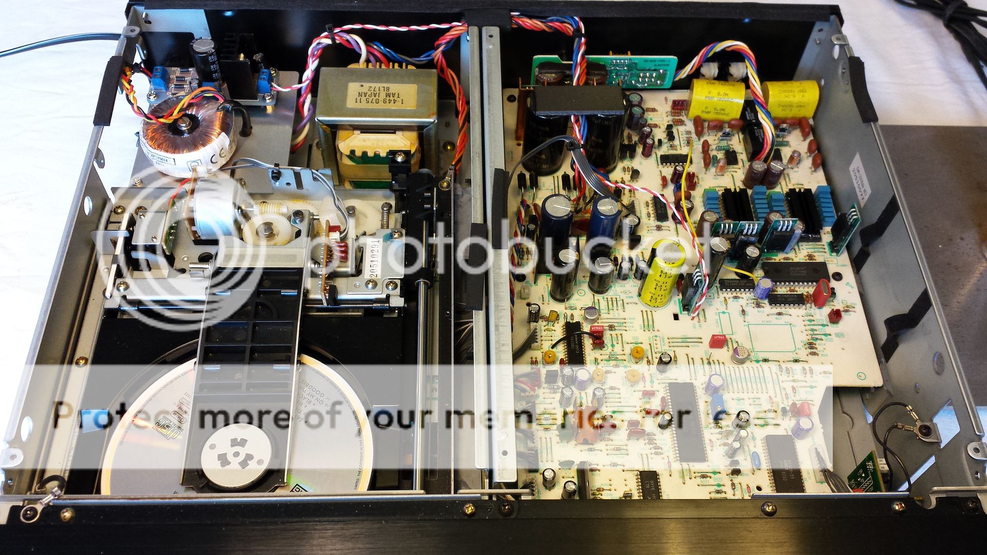
First up heres an overview:
Underside of the laser mech:

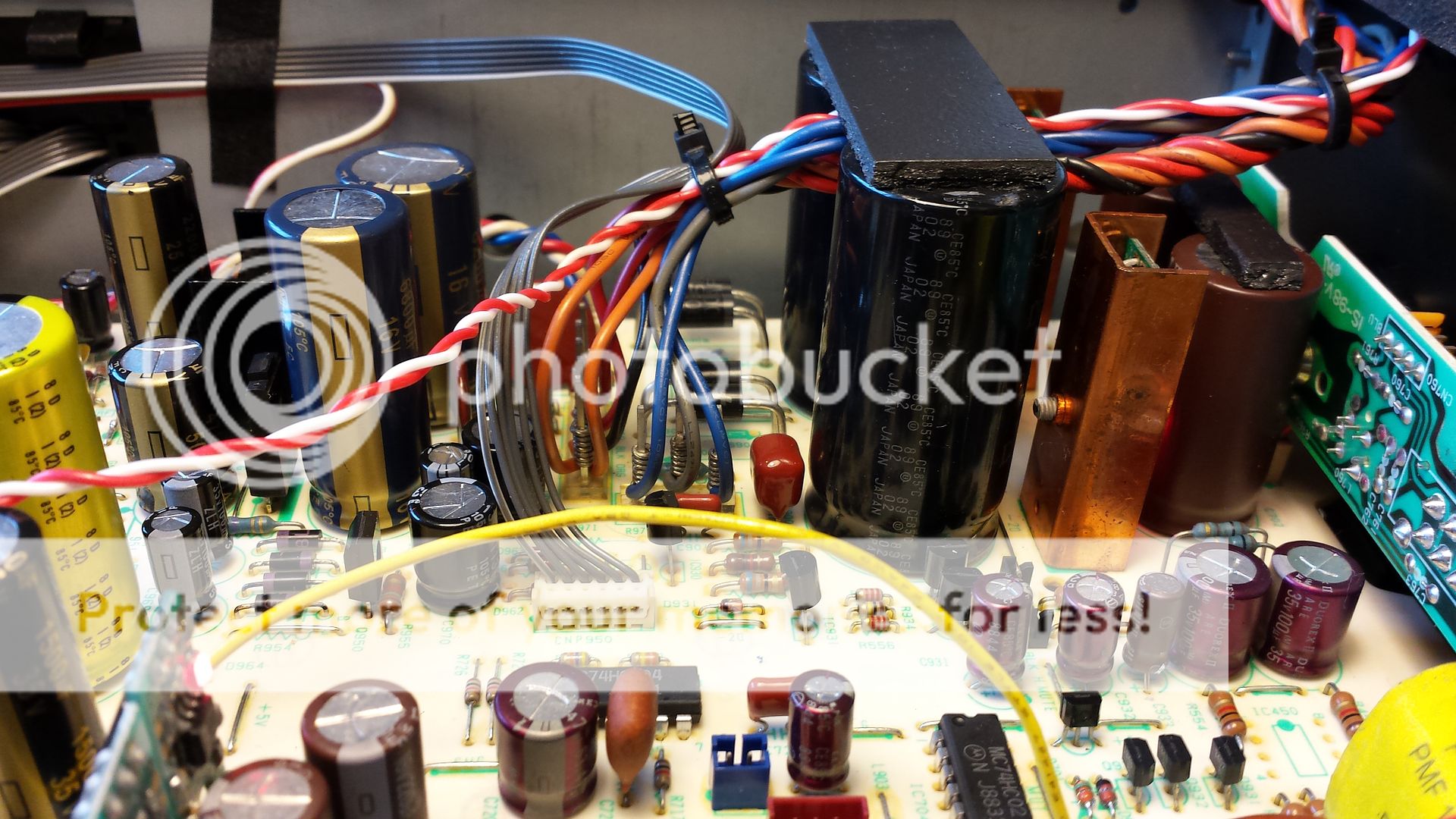
Left to Right: Beefed up capacitors in the digital/servo power supply (Panasonic FC and FM). Schottky diodes for the output stage/analogue section. Huge 6800uF Elna Duorex filter caps for the output/analogue section. Copper heatsinks housing Fidelity Audio Spower discrete voltage regulators (analogue +/- 15v). 1000uF Elna Simlics after the regs.
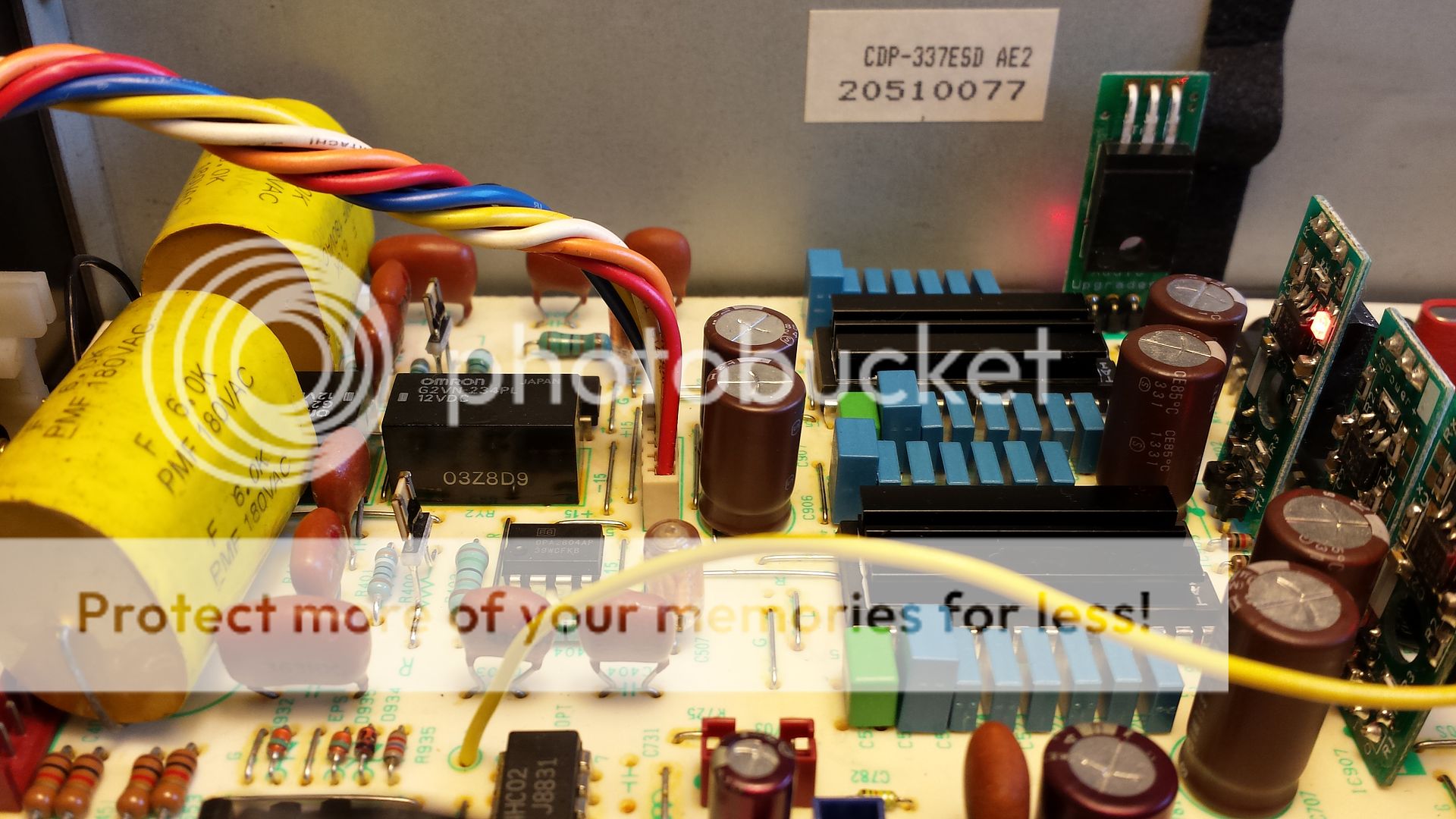
The business end! Left to right: Unbranded axial polypropylene film caps on the output in DC blocking role. The black boxes are muting relays (not transistors!). The turquoise coloured resistors downstream of the DACs are Takman metal film with the exception of IV feedback resistors which are Charcroft Naked Z foil. Op-amps are Burr Brown OPA2604 soldered direct (no sockets) and the power supply rails for the op-amps are decoupled by 100uF Elna Silmic.
Hidden under the heatsinks are the DAC chips which have been swapped to matching serial number Taiwanese manufactured TDA1541A from 1998 which to me are the best sounding. The bit decoupling caps are 220nF polyester with 1uF polyester on the MSB pins. The DEM oscillator caps are 560pF Wima FKP polypropylene film/foil.
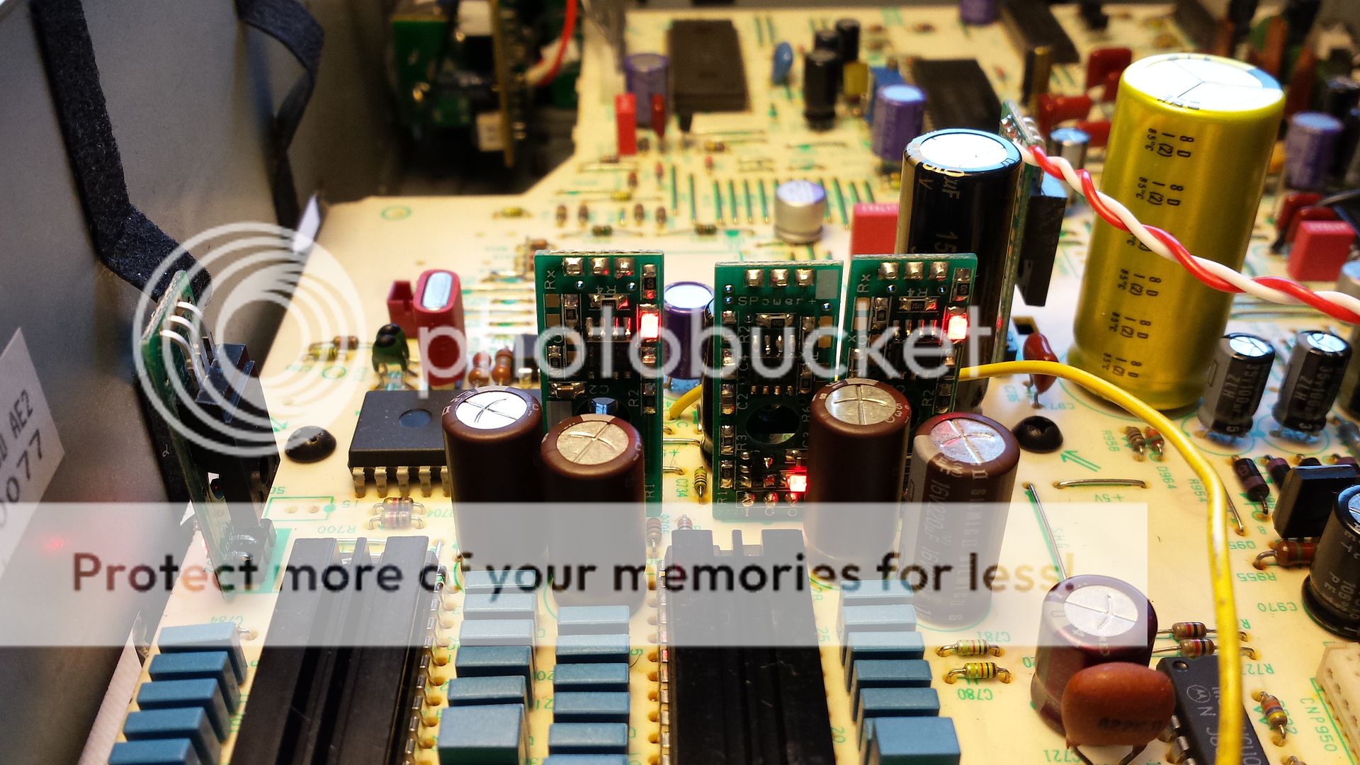
Each TDA1541A has its own voltage regulators and caps for the +5v and -5v supplies. The voltages regs have been upgraded to Fidelity Audio Spower HC and the decoupling caps are Elna Silmic 220uF.
A better view of the voltage regs for the DACs.
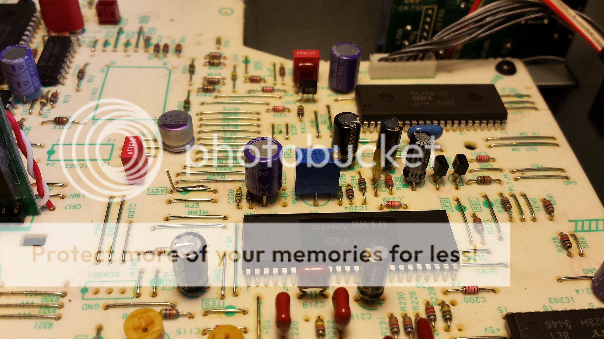
There are also lots of hidden mods under the PCB too. Here you can see some extra decoupling caps for the -15v supply on the DACs (100uF Silmic). The 15uF Oscons tie the -5v and -15v rails of the DAC chips together and the resistors tie each leg of the DEM oscillator cap to -15v (pin 15) to create a simple circuit which is supposed to reduce jitter on the DEM oscillator. Some local decoupling caps for the digital ICs have also been upgraded to small surface mount NPO/COG ceramics mounted under the PCB.

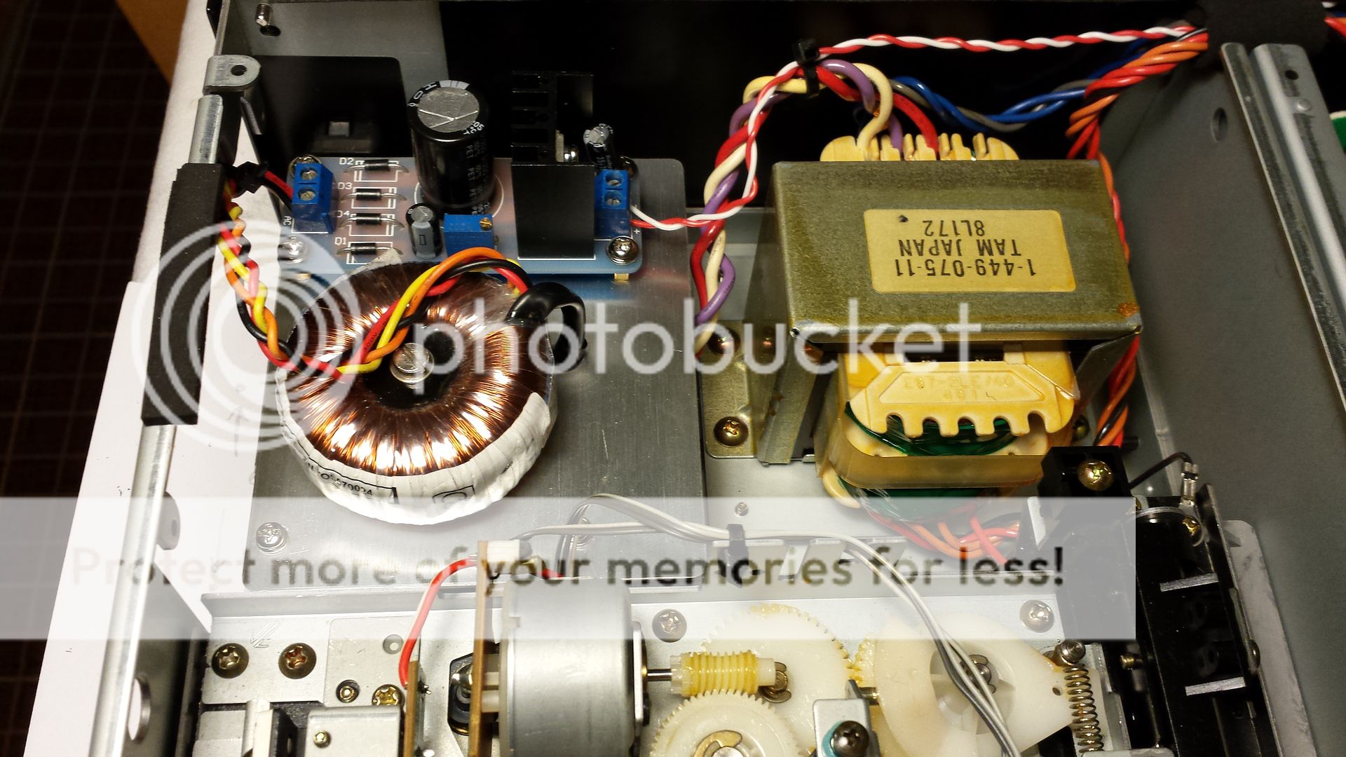
The voltage reg on the left supplies the digital filter chip, and clock circuit. This again is a fancy Spower reg . The caps for the section have been upgraded to 1500uF Pansonic FM, 330uF Elna Cerafine and Sanyo Oscon SP 33uF. The voltage reg is now fed from its own dedicated transformer, rectifier, smoothing cap and is pre-regulated to 12v by an LM317 before being regulated down to +5v by the Spower.
Heres a close-up of the PSU which supplies the digital filter and clock etc. I fabricated this alloy panel which is mounted on brass standoffs and uses only pre-existing screw holes.

I purchased a decent used Tektronix oscilloscope especially for doing the laser alignment adjustments on this player. Focus bias (RF eye pattern), focus balance, tracking gain and focus gain have all been checked and carefully adjusted until just right and the laser mech was treated to a full strip-down clean and re-lube.
I also bought a frequency counter so that I could check and adjust the PLL frequency. To help get this exactly right I fitted a nice new sealed multi-turn trimpot to replace the old single turn one. Youll notice that all of the small electrolytics have also been replaced with top quality new ones and in some cases upgraded to Oscons or film.
My next plan for this player is to fit a upgraded low jitter clock and dedicated PSU which will probably mean losing the small toroid and 317 reg at the top left of the player in order to create some room. Ill keep you posted.
Happy modding!
Mike
I wasnt sure whether to put this post in the classic or DIY section or if it should even go in the system pics thread. The moderators can feel free to move it as they see fit.
The 337ESD is a formidable beast dating from the late 80s back when CD was king and the big audio companies were making CD players built like battleships. The Sony 337ESD is one of the top models from Sony at that time and probably only comes second to the even mightier 555ESD.
This player is huge and incredibly solidly built. The pictures dont really convey the scale but its about twice the size of my old Arcam Alpha 5 and probably four times as heavy!
The 337ESD uses my favourite DAC chip, the TDA1541A. Actually, in the 337ESD there are two TDA1541A DACs arranged in what Sony call staggered parallel configuration somehow supposedly giving 18 Bit performance.
The laser mechanism is the simply superb Sony KSS190A which uses linear motor on magnetic rails for tracking rather than the more common nasty plastic gears. The laser head slides on polished steel rails and rests in a cast aluminium baseplate. The spindle motor is a brushless hall effect item and has a beautifully machined all metal clamp. In fact pretty much everything on the laser mech is all metal. The whole mechanism then sits in what Sony called the Gibraltar chassis which is a special vibration dampening composite of polyester and calcium carbonate.
More info on this player can be found here: http://www.thevintageknob.org/sony-CDP-337ESD.html
And here: http://www.lampizator.eu/lampizator/REFERENCES/Sony 337ESD/sony337.html
Anyway, here are details of my efforts to make the already wonderful Sony 337ESD even better! Ive been very careful not to do anything irreversible and Ive carefully saved all of the original parts in case I ever want to put the player back into stock spec again.
First up heres an overview:

Underside of the laser mech:

Left to Right: Beefed up capacitors in the digital/servo power supply (Panasonic FC and FM). Schottky diodes for the output stage/analogue section. Huge 6800uF Elna Duorex filter caps for the output/analogue section. Copper heatsinks housing Fidelity Audio Spower discrete voltage regulators (analogue +/- 15v). 1000uF Elna Simlics after the regs.

The business end! Left to right: Unbranded axial polypropylene film caps on the output in DC blocking role. The black boxes are muting relays (not transistors!). The turquoise coloured resistors downstream of the DACs are Takman metal film with the exception of IV feedback resistors which are Charcroft Naked Z foil. Op-amps are Burr Brown OPA2604 soldered direct (no sockets) and the power supply rails for the op-amps are decoupled by 100uF Elna Silmic.

Hidden under the heatsinks are the DAC chips which have been swapped to matching serial number Taiwanese manufactured TDA1541A from 1998 which to me are the best sounding. The bit decoupling caps are 220nF polyester with 1uF polyester on the MSB pins. The DEM oscillator caps are 560pF Wima FKP polypropylene film/foil.
Each TDA1541A has its own voltage regulators and caps for the +5v and -5v supplies. The voltages regs have been upgraded to Fidelity Audio Spower HC and the decoupling caps are Elna Silmic 220uF.
A better view of the voltage regs for the DACs.

There are also lots of hidden mods under the PCB too. Here you can see some extra decoupling caps for the -15v supply on the DACs (100uF Silmic). The 15uF Oscons tie the -5v and -15v rails of the DAC chips together and the resistors tie each leg of the DEM oscillator cap to -15v (pin 15) to create a simple circuit which is supposed to reduce jitter on the DEM oscillator. Some local decoupling caps for the digital ICs have also been upgraded to small surface mount NPO/COG ceramics mounted under the PCB.

The voltage reg on the left supplies the digital filter chip, and clock circuit. This again is a fancy Spower reg . The caps for the section have been upgraded to 1500uF Pansonic FM, 330uF Elna Cerafine and Sanyo Oscon SP 33uF. The voltage reg is now fed from its own dedicated transformer, rectifier, smoothing cap and is pre-regulated to 12v by an LM317 before being regulated down to +5v by the Spower.
Heres a close-up of the PSU which supplies the digital filter and clock etc. I fabricated this alloy panel which is mounted on brass standoffs and uses only pre-existing screw holes.


I purchased a decent used Tektronix oscilloscope especially for doing the laser alignment adjustments on this player. Focus bias (RF eye pattern), focus balance, tracking gain and focus gain have all been checked and carefully adjusted until just right and the laser mech was treated to a full strip-down clean and re-lube.
I also bought a frequency counter so that I could check and adjust the PLL frequency. To help get this exactly right I fitted a nice new sealed multi-turn trimpot to replace the old single turn one. Youll notice that all of the small electrolytics have also been replaced with top quality new ones and in some cases upgraded to Oscons or film.

My next plan for this player is to fit a upgraded low jitter clock and dedicated PSU which will probably mean losing the small toroid and 317 reg at the top left of the player in order to create some room. Ill keep you posted.
Happy modding!
Mike
")


