teddy_pardo
Trade: Teddy Pardo
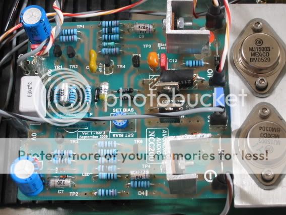
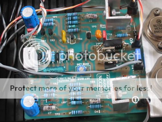
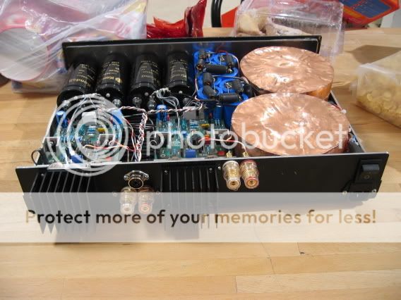
I finally did it (don't know why I waited all this time...), I added regulators to the NCC200 front end. It's easy to do and the improvement is really noticeable. My NCC is powered with 30V AC which gives about 41V DC, the dropout on the NCC diode + 220R is about 2.5V so it's possible to replace them with a 317/337 using the same power supply. Just remove the diode and resistor one each side and use 3 leg regulators instead. The input to the regulators can be taken from the PCB (where the diode was originally connected) so is the ground (use the "star" point of the front end).
I have used 118R and 3K4 resistors to set the regulators to 37.4V, and used just one 10uF 50V tantalum capacitor in parallel to the 3K4 resistor. I hided the regulators below the NCC PCB, and since the wires are very short there's no need for output capacitor (the NCC already has a capacitor+bypass capacitor), I didn't use an input capacitor either.
For the V+ side I've used LT1086, and for the V- LM337AT. Don't worry about the voltage limits, these regulators are only limited by the dropout not by the voltage they regulate. In this case it's only about 2.5V and they actually remain cold.
As for the idle current settings, you need to add about 12mA which is the additional current of the regulator, so set it to 50-52 mA instead of the original 38-40mA
The NCCs are awesome even without any additional regulators, but this improvement is really worthwhile. I wonder why Les didn't do it in the first place. Les?
Some other tips for those who build NCCs:
1. Follow Les recommendations one-by-one wrt components!!!
I built my NCC initially using the part list published here on PFM. This list is using some "economic" parts. When I replaced the capacitors by polystyrene (from LCR) / silver mica, and the output resistors by Maggit non inductive the difference was big. Don't save on these components!
2. Power supply
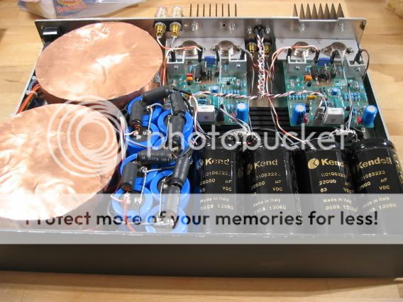
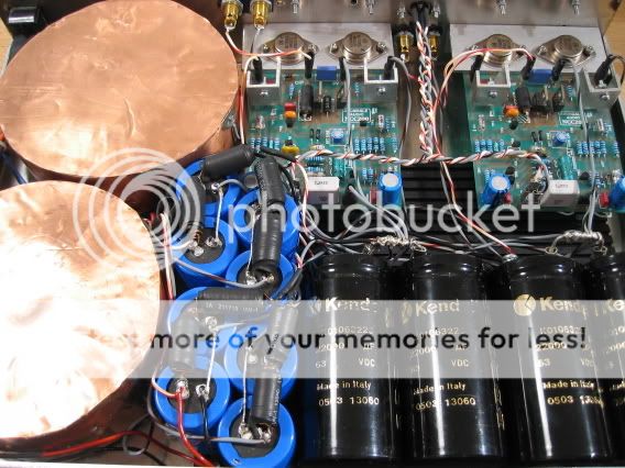
For the power supply I tried first 22,000uF Kendeil which were good, then I tried to build a CAP6 clone using BC 10,000uF capacitors (I think it was 054 series) but it wasn't as good, at last I replaced the last capacitor in the CAP6 clone by a 22,000uF Kendeil (10mF - 10uH - 10mF - 10uH - 22mF). That's the best combination! Try it if you have some room in your case.
Teddy
I have used 118R and 3K4 resistors to set the regulators to 37.4V, and used just one 10uF 50V tantalum capacitor in parallel to the 3K4 resistor. I hided the regulators below the NCC PCB, and since the wires are very short there's no need for output capacitor (the NCC already has a capacitor+bypass capacitor), I didn't use an input capacitor either.
For the V+ side I've used LT1086, and for the V- LM337AT. Don't worry about the voltage limits, these regulators are only limited by the dropout not by the voltage they regulate. In this case it's only about 2.5V and they actually remain cold.
As for the idle current settings, you need to add about 12mA which is the additional current of the regulator, so set it to 50-52 mA instead of the original 38-40mA
The NCCs are awesome even without any additional regulators, but this improvement is really worthwhile. I wonder why Les didn't do it in the first place. Les?
Some other tips for those who build NCCs:
1. Follow Les recommendations one-by-one wrt components!!!
I built my NCC initially using the part list published here on PFM. This list is using some "economic" parts. When I replaced the capacitors by polystyrene (from LCR) / silver mica, and the output resistors by Maggit non inductive the difference was big. Don't save on these components!
2. Power supply
For the power supply I tried first 22,000uF Kendeil which were good, then I tried to build a CAP6 clone using BC 10,000uF capacitors (I think it was 054 series) but it wasn't as good, at last I replaced the last capacitor in the CAP6 clone by a 22,000uF Kendeil (10mF - 10uH - 10mF - 10uH - 22mF). That's the best combination! Try it if you have some room in your case.
Teddy
")