advertisement


Reduced preamp tube lifespan on one channel

DrTom

Member
Hi all,

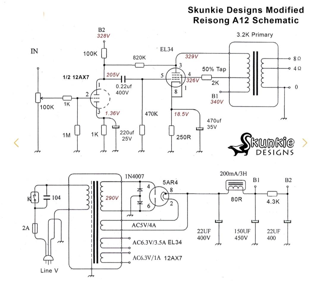
I have a Reisong A12 (modified with the popular 'Skunkie' mods) which runs 12ax7 preamp tubes, a 5AR4 rectifier and el34 outputs.

I had the right channel 12ax7 fail about a year ago... Still worked but looked dimmer and produced roughly half volume. Had maybe 500 hours on it. Figured they were cheap Chinese tubes so no big loss.

Replaced both channels with Sovtek 12ax7lps which now have maybe 3-400 hundred hours on them and the same thing has happened. Volume is about half on the right channel... Swapping the 12ax7 moves it to the left side, so definitely the preamp tube that's diminished.

Any tube officianandos have a clue as to what might be causing it before I go poking about inside?

Ta
 
That is a very short valve lifespan for a small signal valve, even accounting for modern production not being the best. I’ve had the same set of vintage Mullards in my Verdier pre for a decade or so now and they still all test strong.

I’ve never heard of your amp. If it is a Chinese import check the voltage rating. If it is stated at 220V it is almost certainly being over-volted on UK mains, which is typically 230-245V. This will impact what happens the other side of the main transformer and can certainly cook valves prematurely. I’d personally only buy a valve amp that is fully specified for UK 240V use.

That said it may be fine and just be fluke/bad luck with a couple if specific valves. Some modern tubes are just poor, though I’d expect the Sovteks to be ok. Even so if you are electronics competent I’d get the valve pin-out and measure some voltages. The spec for an ECC83 is easily found so you should be able to spot anything off.
 
Well, even with 450 V supply as in my 1983 l’Audiophile phono preamp supply ECC83’s really last forever.
Do you have any schematics?
 
Does the right channel sound low and/or appear dim from the moment the amp is switched on?
If you pull the good valve, so you are only playing the right channel, does the music otherwise sound right?
What is your source?

Probably the commonest failure mode is for a/the heater to pack up and usually, not always, the two heaters in double triodes are run in series, so if one dies (goes open circuit), both die. If they are in parallel in your amp, then one heater may well have died. (Don't forget that most small triodes are two identical valves in one bulb - double triodes.)

If they are in series, over-volts would lead to evaporation of the heater elements, which would lead to them being high resistance, which means reduced power - watts = (volts squared)/resistance

If it is the heater, based on the fact that two valves have failed in the same position within no real time, logic would say that the heater supply is over volts on that position, which is difficult to believe however...............................
 
Last edited:
Hi all, thanks for the replies. Rushing around at the mo but will have a proper read this evening.

Modified schematic is here -

Pj7gDvp.jpeg


I guess one option would be to rewire the pins on one of the 12ax7 to use the opposite triode and double the lifespan of the tube, but addressing the underlying issue would obviously be preferable.
 
6.3V supply for the ECC83's would mean parallel connection of the two heaters in each valve. Except that it appears that only one is used.......

I'd check that first, at the socket for each ECC83. You need to find which pins online, there will be 3 to each valve, a common and a 6.3V supply for each triode, each valve. Beware high voltages, if you are unsure, leave well alone.

I know the barest basics here, but why would any sane person design an amp' to use just half of a double triode?
 
I know the barest basics here, but why would any sane person design an amp' to use just half of a double triode?

Surely we are just looking at one channel? The other will use the other half. That’s how it usually works anyway.
 
Yikes! I have so many questions! I’ll start with WTF is going on with the blue resistor to the left of the centre valve-base which has been bypassed with a solid wire?

PS I’m really cringing here, there is just so much in there only a light jiggle away from shorting-out.
 
Surely we are just looking at one channel? The other will use the other half. That’s how it usually works anyway.


I was reading that there are two, one for each channel. There are two ECC83 and I only see half of one in the diagram for the modified amp'
Going back to the linked circuit diagrams, I recall (have not rechecked) that the original circuit had the two triodes in parallel..
Granted, left and right would normally be on the two triodes in one valve.

It does look at best, something of a fire hazard, it has to be said.

Edit - just one triode in each is wired in in the photo'. 4, 5 and 9 are the heaters, 9 being the centre tap.
 
Granted, left and right would normally be on the two triodes in one valve.

It seems a pretty common way of working, e.g. my JC Verdier preamp has three dual triode valves in both the phono stage, and the line stage (six valves total). Each stage is split one left, one right, one shared. The supplied schematic is drawn very like the one upthread detailing one channel with a half valve pictured for the shared ones.
 
Added to my previous post since your answer - check what is wired in, on the ECC83s. Only one triode on each

Check also the linked circuit daigrams - original v. modified in the DIYaudio discussion..
 
Perhaps the worst thing is that you do not need any understanding of valves or electonic circuits, beyond much more tha Ohm's law, to have a quick look and say that it is a horrendous mess, and potentially dangerous.


advertisement


Back
Top