advertisement


Quad FM3 no power - where to start?

kasperhauser

pfm Member
As stated. Plug it in, nothing happens, not even momentarily. Fuse is good.

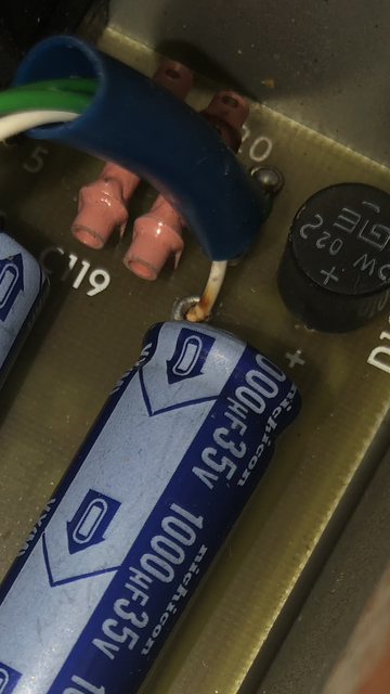
I saw an old thread here that suggested caps and rectifier diode are likely suspects. I see three Nichicon caps and they all look outwardly fine.

Suggestions? “Send it to Quad” is already in play, but I’m hoping to rule out at least a few simple options that don’t involve a 10,000 mile round trip.
 
On these units, the cover next to the mains inlet not only indicates input voltage, it is reversible, with the voltage conversion slide switch having to be positioned appropriately in order to fit though the offset cutout in the cover and match with the voltage labelling on that side.

With the unit unplugged from the mains, try removing this cover and sliding the switch back and forth a few times. If there is a mains connection issue, this might just solve it.
 
What country are you in? Probably not UK (because you said 10000 miles away) but maybe US because you said miles, not km. Anyway, are there any other possible fuses you could have missed? If UK, one in the plug?

If you feel comfortable using a multimeter you could put it in VAC mode and measure the transformer secondaries. I wouldn’t measure primaires, mains voltage, etc. unless I really trusted my multimeter and my own abilities.
 
I just remembered you mentioning also having 33 and 303 over on your 'Meridian M20 in the house' thread @kasperhauser.

As FM3 is intended to draw power from 33 (and assuming that this is how you have it connected), if you do have a multimeter handy, it would be prudent to check that there is mains on the line from the pre-amp before assuming the tuner to be faulty.

As @booja30 described, setting an auto-ranging multimeter to VAC and then inserting one probe into hot and the other into neutral of the tuner end sockets of the Bulgin plug (there is no ground connection to the tuner via the third pin) should let you know if the tuner is getting power. Red or black into either hot or neutral, doesn't matter. Just remember to hold both probes by the insulators with one hand only (i.e. don't give the mains a chance to cross your heart!)
 
Ok, some good things to try.

I pulled the plastic plate and worked the voltage selector switch a few times. Still nothing though. Also, apologies, I’m not sure what you mean by the FM3 getting power from the 33; they both have identical round, 3-prong power inputs on the back and they arrived with two identical 3-prong to US outlet power cords. Maybe later model or North American spec? I’ve just been plugging it straight into the wall.

As for my multimeter skills, they are not extensive, but I’m careful so survivability has thus far been sustained. Also, I’m in Eugene, Oregon, US of A, so no redundant safety measures like cord fuses to check.
 
The tuners used to come with both a round Bulgin to 2 x flat blade connector power cable to go between tuner and pre-amp, as well as a Bulgin to standard power plug cable to go between tuner and wall. These allowed the tuners to be used with or without the 33.

Having said that, if you have a look at the two flat blade power output sockets round back of your 33, you are likely to find that they look quite familiar to us North Americans.

Flashback used to do one with a shaved down 2-pronged flat-blade plug for the 33 end.

2-pin-quad-33-mains-outlet-3-pole-mini-bulgin-plug-cable.jpg


P.S. If you are testing your power cord, Bulgin plug L and N are either side of the locating notch.
 
Well, the power cords (which look just like the picture above) are both fine - both work with the 33. I suppose next thing to do is open the FM3 and see if that power is making it past the 3-prong input. Will try that this afternoon.
 
It might also be the transformer itself. I have had to replace a faulty one in one of my FM3. At the time I had searched around and it seems that we can no longer get one from the manufacturers of the time. They have changed ownership several times so the Dagnell of today is not the old supplier to Quad.

SO - this a possibility instead.
Hammond 166E18 - its centre tapped and supplies 18v.
Its rated at 5.4VA - 0.3amps.

https://www.hammfg.com/electronics/transformers/power/166

The original Dagnall was rated at 6VA.
This Hammond one is close enough.
The mounting bolt spacing is slightly closer so one new bolt hole would have to be drilled.
 
Suggestions? “Send it to Quad” is already in play, but I’m hoping to rule out at least a few simple options that don’t involve a 10,000 mile round trip.

If you get to the point of contemplating a huge round-trip it would likely be cheaper to source a working but cosmetically challenged example as a donor unit. FM3s don’t tend to go for much in the UK as radio is far less of a thing than it was and there were huge numbers made. It looks like you can get one on eBay for £30 if you are patient and don’t care much about physical condition. That’s likely less than a transformer!
 
Ask Rob Flain at Quad. He might have the part in stock.
I recently purchased a 405 transformer from them, even though the original manufacturer is probably long gone — much cheaper than those toroidals from Dada et al and totally silent.
 
You have proved the mains lead and plug are good.
Next is check you have continuity across the transformer. Put your meter on 200Ω or 2KΩ range, with the lead unplug from the mains and plugged into the FM3, measure the resistance from the 'hot' pin and 'neutral' pin. It should be a low resistance. If it is open circuit the transformer is faulty or you have a bad connection.
If it is a low resistance you will have to measure the voltages inside the tuner. There are plenty of circuit diagrams on line.

Right. Following your guidance, I see 112 ohms resistance across those pins. I take it that means power is likely reaching the transformer, and the next step is to ensure that power is exiting the transformer appropriately?
 
Right. Following your guidance, I see 112 ohms resistance across those pins. I take it that means power is likely reaching the transformer, and the next step is to ensure that power is exiting the transformer appropriately?
While you have your meter out, suggest testing the fuse regardless. These can sometimes look fine but measure OL.
 
Unbolted the transformer from the casework just to have a looksee underneath and saw this:

1-EF61-DBA-6-A8-B-4293-87-AA-0-C82036-F2-EBE.png


That white wire is one of three exiting the transformer (there are also two green ones). The discoloration shown is the only suspicious sign I see anywhere - everything else “looks” ok.
 
The schematic indicates 2 transformer secondary side leads connecting either side of the bridge rectifier with the third connected to ground. As you've 2 x green and 1 x white, the latter is likely to be ground, and if it has disconnected would leave zero voltage to the board. With what appear to be burn marks on the insulation, perhaps there is (or rather, was) a cold solder joint where this connects.
 
I do not think the brown stain is significant, might be flux from the soldering.
Next measurement will be power on so be careful where you place the transformer. You need to get to the components beneath it, so carefully rest it on some insulating material.
You need to get your meter probes on the solder rings that the green and white wires go to.
Select 20 volts AC range, now put one probe on the white wire 'ring' then touch each green wire ring in turn, you should get a similar voltage from both. Tell us what you get. If they are the same / similar the transformer is okay.
If that is good now measure the voltage on the 1000uF blue caps (C113 and C114) next.
Meter on 20 volts DC, Black probe on the Negative end and the Red probe on the Positive end lead, you should get a similar voltage across both capacitors. Note the caps point in opposite directions. The white arrows printed on the caps point to the Negative lead.
Again let us know what you get.


advertisement


Back
Top