advertisement


Pushing the OPA604

Dan K

pfm Member
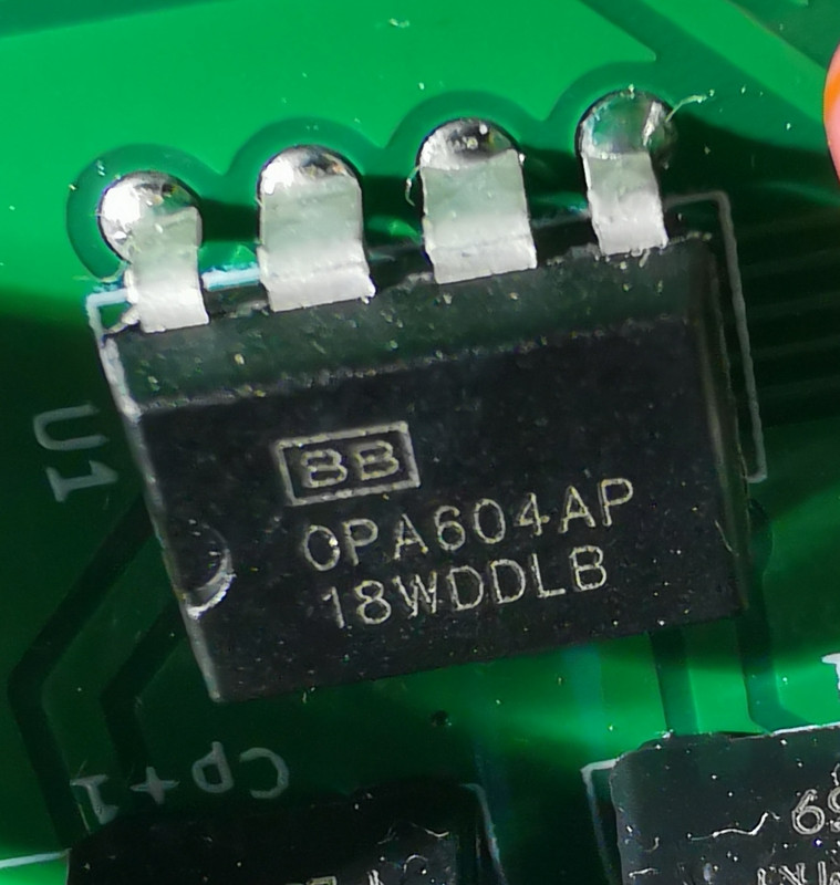
I'm trying to run a BB OPA604 as a front end to a Pass M2 power amp..

As you all know this will involve +/-24V rails and I'm assured the 604 will be happy with this, however.. I have +/-24.5V.

I've read a few comments on fora claiming that the 604 is actually fine up to 50V (+/-25V)

Any experience of running this Opamp at its max for years?

What's the failure mode like? I'll take faint sizzle followed by silence, but obviously not a loud crack and smoking tweeters.

Thanks
 
Easy answer - add a diode in series, maybe two , with each supply; knock 24.5 down to maybe 23.7, 23ish, follow with decoupling cap to 0V - which will reduce output-stage ripple effect on the opamp PSRR. Double-win :)

Any given example of [opamp] might well stand +10% on supply - I've gone that far +, on a few others - but only on test: and - then the failure mode, is undefined.

How-much, might a worst case, fails to full rail-voltage, failure cost you..?

Examine & protect against that aspect, first.

OH - and how much headroom, is pushing such a thing that far, really going to buy you? If it's the difference between, say, 60 vs 50w output max - == not worth having.
 
.. I've not knowledge or real interest in this amp design, but - as with most others: a dab of C-R-C as front -end filtering for that opamp with R of 10-50 ohms, as you determine required; /and/ maybe a zener to 0v after that R, (in this case, say 22v nom) to limit peak exposure to c 22-24v, could serve several aspects , well:
- Limiting peak Voltage exposure to the opamp (what happens when you switch the amp off, and output bias falls fast, but decoupled rail voltage /might/ lift locally?)
- low-pass of raw supply, independant or load on output stage ...

etc.

Plot a diagram of what you are likely to see, vs. what might go Rong.
Fixing Good speakers, is expensive...
 
Absolute max is quoted as +/-25V perilously close to +/-24V. A colleague once designed a circuit which used a comparator IC running on regulated +/-15V rails, the IC had absolute max quoted as +/-16V. Random failures of the IC started to occur and I dropped the supply to +/-12V which completely cured the problem.

In a steady state there would have probably been no problem. But, as Martin says, once you start switching on and off there may be transient issues.
 
Checked the rail voltages today whilst at home, as mains is usually slightly lower during the day.

48.5V, but from cold the PSU spiked up to 51.2V for a split second.

Does the OPA604 care?
 
Are you able to implement Martin's suggestion above of the CRC to drop the voltage, and possibly the zeners, so the output voltage is not affected by any input spike?
 
A couple of options are available..

1) keep the amp component count to a minimum and replace the active rectifiers with std items. There are a pair of local 0.1uF MKP caps at the OpAmp legs and that's it. Max voltage is desired to get the most gain.

2) cut circuit tracks and add SMT resistors + 22uF MLCC cap under the 0.1uF MKP = slightly less overall gain. I've actually got some 10uF lytics and some spare 39R 1/4w resistors.

I'm not sure that the front end actually sees the voltage spike from switch on/off - more checking required
 
Last edited:
Informal rule of thumb for long term reliability would be 'Perfectly fine up to [ recommended max - maybe 10% for tolerance on PSU rails habits.]
At +/-22V OPA604s last forever, and plenty of commercial products, not just audio, do/did exactly that
(PS &for any other opamp, too...)
 
Thanks Martin, Spec. sheet does rate the 604 at 48V with an absolute max of 50V. For the various parameters measurements are provided up to 48V. Have to assume that 50V is a 'Never exceed' value, intended for transients.

I was hoping an ex Naim type would be able to recall how they rigged one up at 50V and left it power cycling for 6 months - that sort of thing

Any comments on the authenticity of the item in the pics? The lack of the small dished dot does concern me


advertisement


Back
Top