advertisement


pfm Ogre I

Hi James, thanks for chipping in, I was hoping you'd come along. I'll get you more exact values for the filters. When I got the components from Wilmslow Audio, they have changed some of the component values in the circuits to reflect what they actually sold. Not ideal I suppose. If I remember correctly though they changed the 2.7mH inductor in the LP for a 3mH, also it's definitely an air cored one not a ferrite core as per the schematic.

I probably chose the wrong time to post about this, I'm going away at the weekend and it's unlikely I'll find time to take the crossovers out to note the values for you. I'll e-mail Wilmslow and see if they know, that may be quicker.

When I asked them to supply the components they wanted to use a different crossover completely, they said they didn't think the Zaph one was very good, They wanted to keep the HP the same with the same crossover point (1.8 ish) and move the LP crossover point up to 3Khz. and add a shelving filter. I wanted to stick with the known design though. I guess the Zaph design doesn't use the shelf as the current cross over point filters at least part of the bump out.

I'll get back with the values as soon as I can but for the time being some box sizes in addition to those i have already spoken about further up the thread.

Sealed 30.6 L box with all braced and driver volumes accounted for.
Wool stuffing to about 80%
23cm baffle

Thanks James.

Stefan
 
When I asked them to supply the components they wanted to use a different crossover completely, they said they didn't think the Zaph one was very good, They wanted to keep the HP the same with the same crossover point (1.8 ish) and move the LP crossover point up to 3Khz. and add a shelving filter. I wanted to stick with the known design though. I guess the Zaph design doesn't use the shelf as the current cross over point filters at least part of the bump out.
Unless Wilmslow had in fact built JK's design and compared it to their version of the same loudspeaker sans XO, they are in no position to judge. In any case, you can't "keep the HP the same with the same crossover point and move the LP crossover point up to 3Khz". You either move them both up, or keep them where they are.

You are using premium drivers and not getting anywhere near the best out of them. That is the real shame.

The tweeter you've selected is very slightly different from the one JK specified. That may have a material impact. But I suggest straying from JK's crossover formula, despite Wilmslow's recommendations, is not an ideal starting position. The 3.0mH inductor is not a problem. You can easily unwind it with the help of an LCR meter to get 2.7mH. Beware it doesn't take much unwinding to lose 0.3mH. Is the inductor DCR close to what JK specified?

I wish I could help you more, but at remote distance, the best I can do in the absence of measured data is to make educated guesses. Let's take it one step at a time, starting with resetting the XO to JK's specs.

James
 
In any case, you can't "keep the HP the same with the same crossover point and move the LP crossover point up to 3Khz". You either move them both up, or keep them where they are.

The reason that I have come back to PFM rather than following their idea, seemed a very strange suggestion to me, I even questioned it in case I was getting the wrong end of the stick:(

You are using premium drivers and not getting anywhere near the best out of them. That is the real shame.

My thoughts exactly.

The tweeter you've selected is very slightly different from the one JK specified. That may have a material impact. But I suggest straying from JK's crossover formula, despite Wilmslow's recommendations, is not an ideal starting position. The 3.0mH inductor is not a problem. You can easily unwind it with the help of an LCR meter to get 2.7mH. Beware it doesn't take much unwinding to lose 0.3mH. Is the inductor DCR close to what JK specified?

I've no idea of the DCR, JK specified a +/- .2 DCR ferrite core from memory, the one that Wilmslow supplied was an aircore one that they don't publish DCR specs for. How can I measure that? I don't think my DMM is up to measuring that low. I'd be very surprised if the inductor was anywhere near the DCR I asked for. I could always source another coil with a ferrite core that was the correct DCR if you thought that was for the best. Could that contribute to what i have described?

I wish I could help you more, but at remote distance, the best I can do in the absence of measured data is to make educated guesses. Let's take it one step at a time, starting with resetting the XO to JK's specs.

You are helping loads James, lets get back to the correct values first as you say.

The driver does have stuffing behind it, as does the rest of the box BTW. I wondered if I might benefit from some diffraction foam wedges behind the woofer? But like you say, lets start with the crossover first.

Thanks a bunch,

Stefan
 
The DCR of the woofer coil won't present the problems you're hearing, but the wrong value of inductance can.

If you have stuffing behind the driver, then 'diffraction foam wedges' are not necessary. Try increasing the density of the stuffing, but keeping a clear 4-6 inches behind the driver, and see what happens.

James
 
Hi James, wilmslow never got back to me with thier component swaps they made so i'll have to take them apart, i'll definately not get time before I go away, sorry. I'll post over the Xmas holidays. Thanks for all your help so far.

Stefan.
 
Hi James, sorry i've not got back yet, everything has been a bit crazy and my usual amp is out of action at the moment. I didn't want to make the changes without a known reference for listening. I'll get the amp back up and running and then get back to you.

Stefan
 
Hi James,

Sorry for the delay!!

I've finally got the speakers apart to check the component values again. In fact the coil in question was the correct value after all. The only component value that is different is the padding resistor for the tweeter. They have changed this to a value of 4.7 ohms which i assume was done to account for the slightly lower sensitivity of this driver. I know that they definitely haven't modelled any of this though.

I adjusted the stuffing as you suggested, this has had quite a dramatic effect on opening up the soundstage and they now have greater dynamics and scale which is great :) no change to hardening of the mids though :-(

I'm sure there is a solution to this, maybe i should knuckle down and learn LspCad, i'll have to look into how much a license is, I suppose I need some measurement kit as well. Unless i can just pay you (James) to model the crossover for me:D
 
Stefan,

I can assure you a copy of LspCAD and a calibrated mic would cost you a lot less than return airfares for me to come to you. I can always use T/S parameters to model the response based on the XO you're currently using and see what anomalies are apparent.

If you can post the full XO schematic and component values, I will give it a crack.

James
 
Stefan,

I can assure you a copy of LspCAD and a calibrated mic would cost you a lot less than return airfares for me to come to you.

My wife already thinks I've done some crazy things trying to get a better sound, flying you here to feck about with it might upset her a little!

If you can post the full XO schematic and component values, I will give it a crack.

James

Great, I really appreciate that. Of course I'll pay you for your time or make a donation of whatever. I'll get somthing up tonight when this lovely sunshine and the long list of DIY jobs has come to an end.

Stefan
 
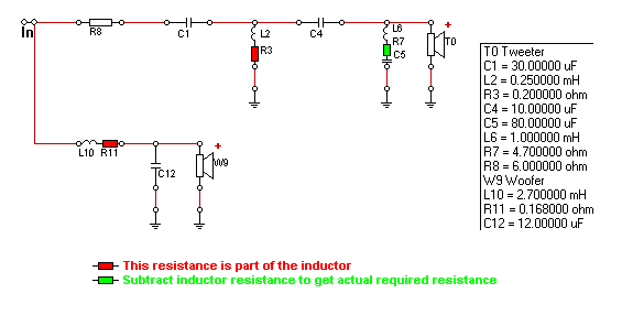
Right, as promised, a schematic with all the component values. The cabinet sizes are further up the thread and it is stuffed to about 70% volume. Anything else you need I am just here.

ZRT-2way-crossover.gif


My actual Values are as follows

C1 30uF
L2 .25mH
C4 10uF
C5 80uF
L6 1mH
R7 4.7 ohm
R8 5 ohm
L10 2.7mH
C12 12uF

According to the schematic on Zaph's site R7's actual value should be 4.7 ohms minus the actual value of the inductor, it's definitely 4.7 ohms though.

The padding resistor value is different from the values on Zaph's site as well

Here is a pic of the board FYI

IMAG0101.jpg


Thanks so much for all of your help, hopefully it'll be of help to the rest of the PFM community when we get these singing properly.

Stefan
 
No problem, many many thanks for even bothering to look. Meant to say that all the inductors are air cored.

Stefan
 
Ah, this slipped my mind completely. Been trying to get our house ready for sale in the last couple of weeks. I'll find some time over Easter. Back to you soon.

James
 
No worries James, I know only to well how hard finding time for this can be :)

Thought, you might find this thread interesting, another builder tried to build a sealed version of the ZRT in a 1Cu ft cabinet (28 litres) which is a bit smaller than mine (33 liters without drivers and braces - about 31 with)

Toward the bottom of the thread JK comments that the box may be a little big for sealed and suggests porting it as per his original design. His original design suggests that a sealed enclosure of a reasonable size would work well, he suggests a 20l cabinet.

Now if your modelling suggests I would be better with a smaller cab I could always add a solid shelf or sandbag accordingly.

Thanks again
 
This thread is interesting as well, using similar drivers JK chips in quite a few times and there is quite a lot of data. The consensus seems to be that 20-28 liters is the optimum so maybe i do need to go smaller ( or even give in to the porting :( )
 
Hi James,

Fatmarley of this parish has kindly offered to let me visit him and more importantly his measurement equipment and copy of LspCAD. So if after you have run the numbers with my current configuration you feel the need to get a set of measurements I can do that for you now.

Look forward to your initial findings and thoughts about the box size / porting issue. Hope you have a nice easter and thanks again.

Stefan
 
Hi James,

Just wondered if you'd managed to get a look at the crossover yet. No real rush, I just happened to have the day off tomorrow and could have done some work on it if you had anything to report :)

Speak soon

Stefan


advertisement


Back
Top