advertisement


Olive Hi-Cap Rebuild

jagdesign

pfm Member
I’ve just bought this ‘hi-cap’ kit from a fellow member and today I finally had the chance to look at everything properly. The case is in near mint condition, a good start. The kit includes brand new Kendeil’s and a reconditioned regulator board, everything else is original. I’d like to start rebuilding this asap but have a few questions before I get the iron out.

1. Firstly do I need to use thermal paste on any of the components? The screws for the bridge rectifiers have some white residue which suggests to me there may have been some there before?

2. Is there anything else worth changing before I put it all back together again? I’d like to keep it as original as possible but don’t mind tweaking it slightly if quick gains are to be made.

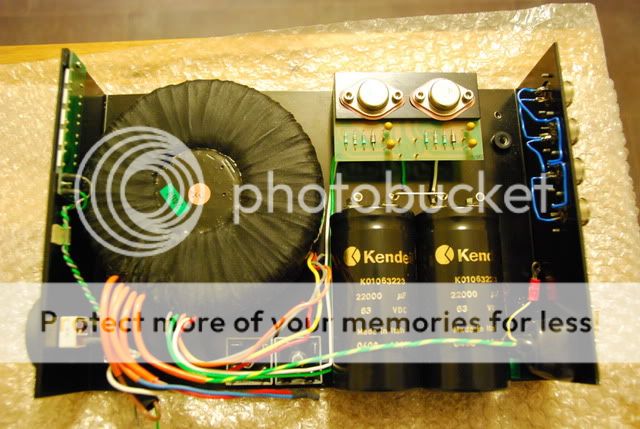
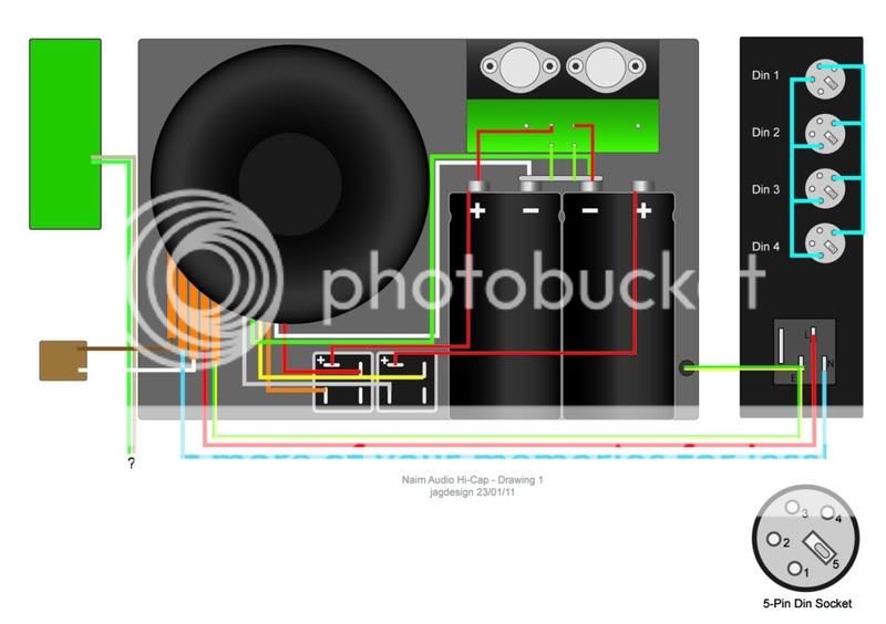
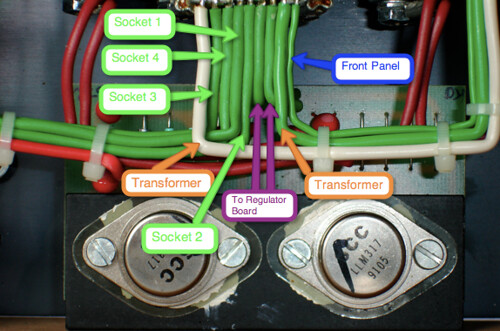
3. I could do with some help in wiring this thing up. I have a basic understanding of electronics but wouldn’t be able to make a calculated guess at what goes where! Below is a photo of the unit itself with components in situ ( I now realise one of the caps is the wrong way around btw). I’ve also knocked up a quick diagram/schematic where, using all the photos of hi-cap internals I could find on the web, I’ve hopefully shown things wired up correctly.

DSC_0046.jpg


Drawing1.jpg


However there are still a few things I’m unsure of:

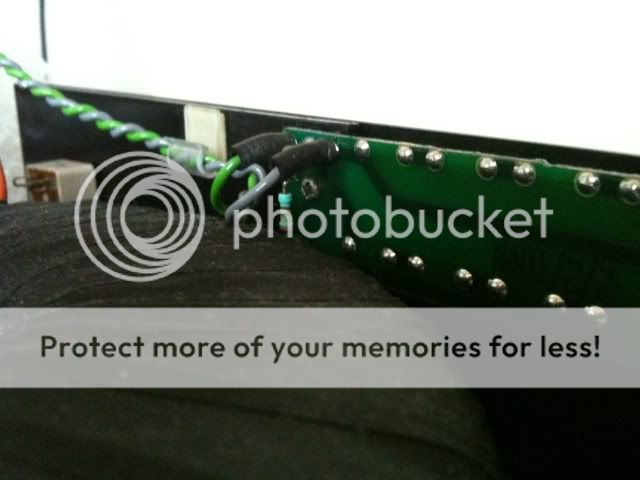
a)The green and grey wires from the LED array board are not connected at the moment, where should these go?

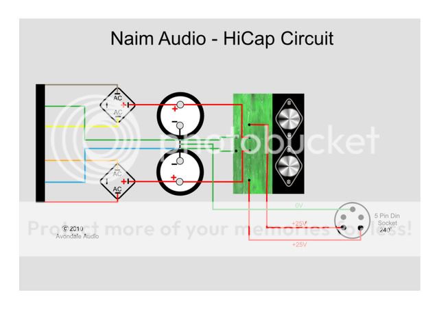
b) I couldn’t really work out the pin configuration on the bridge rectifiers but found another thread on here which mentioned the pin 90 degrees out of alignment with the other three was +ve? Is my wiring on the drawing correct?

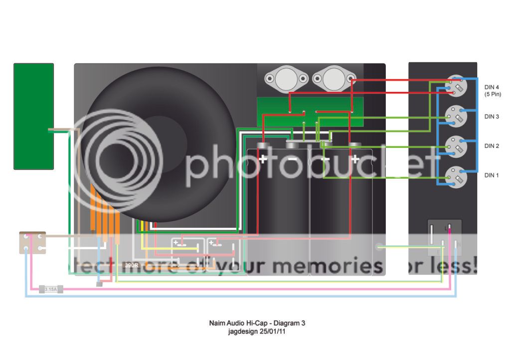
c) I have this diagram from LesW

HiCapLayout.jpg


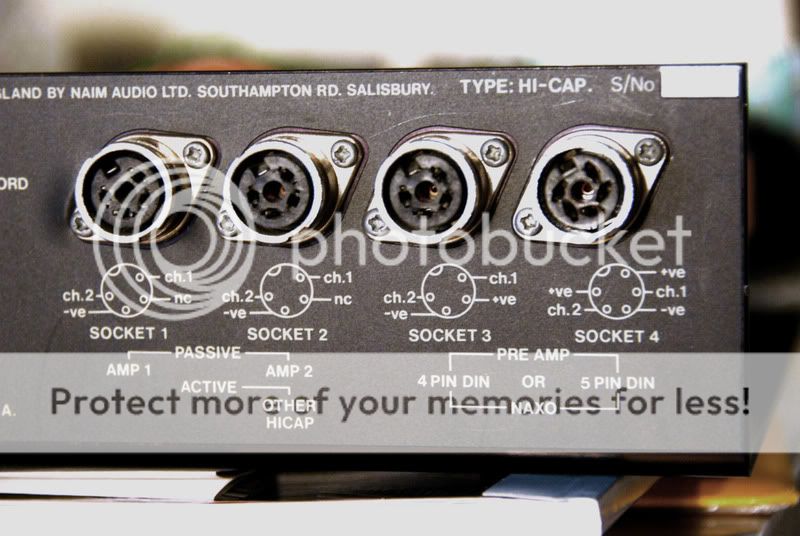
I’m probably being a complete tool, but I’m not completely sure of how his DIN pin configuration fits with mine, and as such I’m not sure how to complete the wiring to each DIN. I’ve also noticed that DIN 1 in my diagram should be wired differently to the other three? Is this correct?

Any help greatly appreciated.

Cheers
 
Hi, I can help with at least some of those queries having recently done something similar with a CB HiCap.

1. As you are doing a 'proper' job, lift the rectifiers, clean off the old gunk with IPA, and apply a thin smear of new heat sink compound before reassembling. It's worthwhile putting a smear between the heat sink on the regulators and the case as well.

2. Other than getting the sockets on the back correct, no.

3. (a) The green wire goes to the star earth between the two capacitors via a 390R (at least 0.5W rated) resistor, and the grey lead goes to the free (negative) terminal on either one of the bridge rectifiers.

3. (b) When you lift the bridge rectifiers you will see that the connections are clearly marked. The two marked AC go to the transformer winding (either way round), the positive goes to one of the capacitors and the negative is left unconnected apart from as noted in 3. (a) above.

3. (c) The HiCap should have three four pin and one five pin DIN sockets. Your diagram shows all four pin sockets. The one on the right looking at the rear panel from outside should be a five pin (240 deg.), I think that equates with the 'Din 1' on your diagram although it's 'Din 4' on a HiCap. Wire that 5 pin as in Les' diagram then connect the two blue wires coming from the other sockets to the two spare terminals on it. They are Ch. 1 and Ch. 2 signal and I'd need to check which goes where. Each of the DIN sockets needs the earth/ground/-ve pin connecting to the star earth. And, for completness, the second DIN from the right needs to have its +24V terminal joined to one of the +24V terminals on the right hand DIN. Do you have the original back panel label detailing these connections and, most importantly, how to wire the HiCap to your system depending upon which components you are using? If not try to find a picture in one of the Naim on-line manuals. I probably have it somewhere and will look if you can't find it.

I also note that the vital mains earth connection (solder tag) seems to be floating free in your photo. This needs bolting down to the chassis and should be the only thing connected to the chassis.

I hope that helps but you really need a picture of the rear label to be sure that you have it 100% correct,

malcolm
 
I think it was Martin Clark who mentioned (somewhere on PFM) that Naim's configuration of the ground wires (and even the gauge of the wire used, I think) was one reason why HiCaps sounded as good as they did. At the time he made that comment, I took a photo of my HiCap ground wiring (from the busbar of the smoothing caps) and labeled where each wire went.

Here's the annotated photo (I'm pretty sure this is correct but maybe others could chime in):

5381039751_b716cb20ae.jpg
 
Hi,

If I was starting from scratch I would turn the smothing caps round the other way to shorten the wires from the caps to the bridge rectifiers. Lots of spikes of current run down these and the shorter the better I find.

Pete
 
I'd just add that you could wire it so that the bridge +ve go as close to the cap as possible so those large charging currents don't travel the length of the busbar.

Mark.
 
James,

I've now worked out all the connections for the sockets but can only draw them by hand. Maybe if you post your diagram we can sort it out from there.

It would be helpful if you could renumber your sockets the way that Naim do with the 5-pin being 'Socket 4' and then '3', '2', '1' counting away from the 5-pin.

The only thing I'm unsure of is the single +24V connection to 'Socket 3' which appears on early HiCaps but, according to the manuals, not on more recent ones. I think it was there to be used with a NAXO 2 or 3 but can be dangerous because if you accidently connect it via a 4-pin SNAIC to a NAP with a +24V output you are in danger of blowing the regulator in the NAP and one of the the two regulators in the HiCap,

malcolm
 
There are two differences between your top diagram and what naim actually do.

The first is that to the regulator circuit furthest right you have connected both the positive supply and ground return to ground. This won't blow anything up but it won't work. you should connect the red wire currently connected to the bus bar joining the two caps to the positive terminal of the cap on the right.

The other difference is in how the mains side of the traffo is wired up.

The way you've done it will work OK but it isn't as good as naim's way since the traffo doesn't get completely isolated from the mains by the switch your way.

What they do is use a DPDT switch and take the live & neutral mains to the white & brown leads into the traffo via the switch. They join the mauve (drawn red on your pic) and blue wires together to complete the circuit.
 
Many thanks guys especially for the extra photos, definitely a big help.

Here's my second attempt, likely to be more things I've overlooked as I'm knackered from work!

Diagram2.jpg


Malcolm, I've had a look at the rear panel on the hi-cap. It looks like DIN 3 does has +24V running to it. This ties in with all the photos I have of other hi-caps.
rear.jpg


Also, the 390R current limiting resistor you mentioned, is this not built in to the LED display board?

Colasblue, my hi-cap does red and blue wires from the traffo joined together. I'm not sure I've correctly interpreted what you stated about the DPDT switch. :confused: 
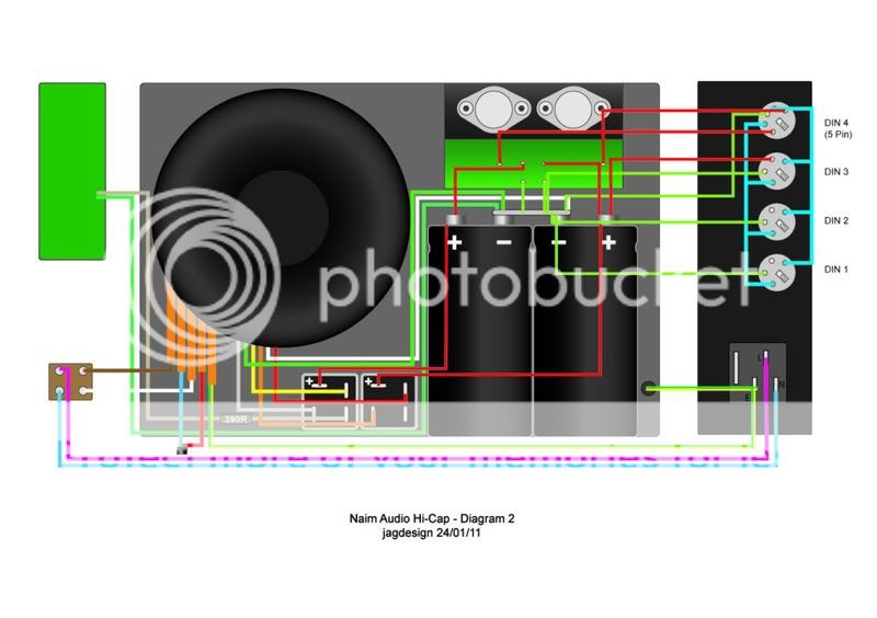
On the diagram I've shown the live and neutral AC IN running straight to the switch at the front, which doesn't seem right as I would've thought the switch should come after the voltage has been stepped down? I've had a look at the photos Hugh put up (thanks again) but it's difficult to see exactly what's going on between the IEC socket, on/off switch and traffo?

Thanks again

James
 
Good morning James,

that's much more like it although I'm not fully awake yet and may have missed something.

The red wire from Socket 3 is incorrect, you have it going to the capacitor which has +37 Vdc on it, it should go to one of the regulated +24 Vdc outputs on the circuit board.

I have a copy of the Naim schematic for an Olive HiCap which was given to me on the understanding that I will not publish it and I can confirm that you need an external 390R resistor for the display. If you look at the NAPS140/3 psu that is fitted to the Olive series NAP140 and NAP180 the 390R for the display is included on the power supply board.

Colasblue and your mains wiring diagram are correct. The incoming mains has a fuse (T3.15A) in the live and then both live and neutral are switched before being connected to the transformer primary. This is standard practice and very important for safety.

malcolm
 
Hugh, thanks again, think I've got it sorted now, see below!

Malcolm, thanks for your help (and patience) with this, hopefully the diagram below is now the final iteration.
Diagram3.jpg

I've dropped the +ve input to DIN3 altogether, can always add it in later. The IEC socket on my Hi-Cap has a fuse compartment so I'll check what's in there. Apart from that it looks like I'm ready to cut some wire!
 
Stackowax - thanks for the pic! Yes exactly. Naim put the centre-tap (0v) returns for each winding right at the relevant cap 0v terminal. This design makes the middle part of the bar as quiet as possible, because the peaky 100Hz charging-current pulses don't pass through the centre.

(Otherwise...) even though the 0v link is quite thick you'd get an extra mV or 5 of 100Hz noise (and harmonics) imposed on all the other '0v' lines. The way Naim wire it really is the 'quietest' possible for this architecture. (If you are really bored you can move the centre-tap wires towards the middle, and see quite alarming things on an o'scope...)

As for wire gauge - just make this 0v link between caps as thick as you can; get the blowtorch out - becasue low impedance attacks the same problem.
 
Is there an electrostatic screen in a HiCap Trafo?

There are five leads in the 'Primary side' group. Four would be accounted for by two windings; in series for 230V and parallel for 115V. What's the fifth wire and what does it connect to. James shows it connected to the mains earth.

Thanks,

David
 
Is there an electrostatic screen in a HiCap Trafo?

Thanks,

David

The later, Nuvotem Talema, HiCap transformer does have a screen which should be connected to chassis along with mains earth as James has shown in his diagram.

I was unsure about the earlier, Holden & Fisher, transformers but, having opened my CB HiCap, I find that it also has a screen that is, strangely, coloured pink. This H & F has black wrapping. There is an even earlier H & F with maroon wrapping which I am not sure about,

malcolm
 
Malcolm,

A useful fact. Thanks.

I am surprised that it is anything more than a basic trafo, having become a bit sceptical of Naim over the years.

David
 
Started soldering yesterday and noticed this resistor on the back of the LED board, I take it that's the current limiting resistor?

photo.jpg


advertisement


Back
Top