
EDIT:
Build manual here: http://www.sael.co.uk/pinkfish/starfish_build_manual_v06.pdf
/EDIT.
I've started a new thread to summarise my ramblings from the 'split rail pcb' thread (see http://pinkfishmedia.net/forum/showthread.php?p=264791#post264791 )
What does it do?
-Fits into a 'shoebox' Naim preamp case.
-Enables 'split-rail' or 'single-rail' power supply operation.
-Provides space for large film caps (smaller electrolytics are also caterd for)
-Implements a revised and updated version of Mr Tibbs's switch-mode psu.
-Uses multiple local regulators.
-Separate power and signal grounds.
-Attention to detail on star grounding.
(321) Gain stage:
 [/IMG]
Uses 2 positive regulators and one negative regulator.
(729) Filter stage:
 [/IMG]
Uses 2 positive regulators and 2 negative regulators.
Local regulators:

One positive and one negative regulator shown.
Pretty standard 3 terminal regulators, with some LC filtering on the outputs.
Overall there are 8 positive and 6 negative regulators used.
Power supply:
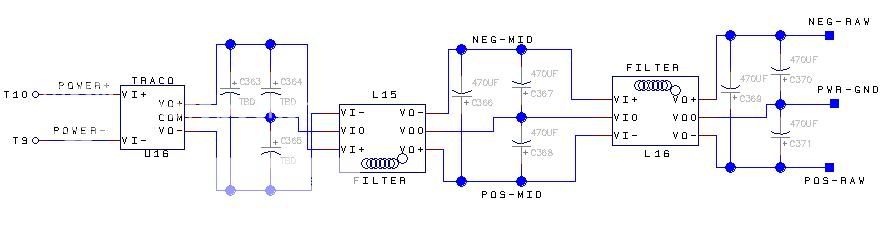
-1)Traco SMPS.
-2)Capacitive filter.
-3)Common mode transformer/choke.
-4)Capacitive filter.
-5)Differential mode chokes.
-6)Capacitive filter.
Output relay:
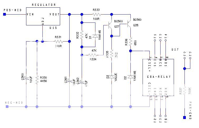
- Relay connections all taken to PCB pins to enable configuration of desired operation.
- Ground connections brought close via resistor.
- Configure operation with wire links.
....And finally, the PCB:

This is 'just a design' at present. It contains lots of ideas that should work, but it has not been built yet.
Please feel free to check through my design, spot errors or ask questions (but preferably not point and laugh...)
Would anyone be interested in 'joining forces' and getting this made as a 'group buy' ?
Jiiim
Build manual here: http://www.sael.co.uk/pinkfish/starfish_build_manual_v06.pdf
/EDIT.
I've started a new thread to summarise my ramblings from the 'split rail pcb' thread (see http://pinkfishmedia.net/forum/showthread.php?p=264791#post264791 )
What does it do?
-Fits into a 'shoebox' Naim preamp case.
-Enables 'split-rail' or 'single-rail' power supply operation.
-Provides space for large film caps (smaller electrolytics are also caterd for)
-Implements a revised and updated version of Mr Tibbs's switch-mode psu.
-Uses multiple local regulators.
-Separate power and signal grounds.
-Attention to detail on star grounding.
(321) Gain stage:
Uses 2 positive regulators and one negative regulator.
(729) Filter stage:
Uses 2 positive regulators and 2 negative regulators.
Local regulators:
One positive and one negative regulator shown.
Pretty standard 3 terminal regulators, with some LC filtering on the outputs.
Overall there are 8 positive and 6 negative regulators used.
Power supply:
-1)Traco SMPS.
-2)Capacitive filter.
-3)Common mode transformer/choke.
-4)Capacitive filter.
-5)Differential mode chokes.
-6)Capacitive filter.
Output relay:
- Relay connections all taken to PCB pins to enable configuration of desired operation.
- Ground connections brought close via resistor.
- Configure operation with wire links.
....And finally, the PCB:
This is 'just a design' at present. It contains lots of ideas that should work, but it has not been built yet.
Please feel free to check through my design, spot errors or ask questions (but preferably not point and laugh...)
Would anyone be interested in 'joining forces' and getting this made as a 'group buy' ?
Jiiim
