advertisement


Naim style rectifier: why?

I got that! I will try to phrase my question differently - sorry if my English is too limited to express clearly what I am after...

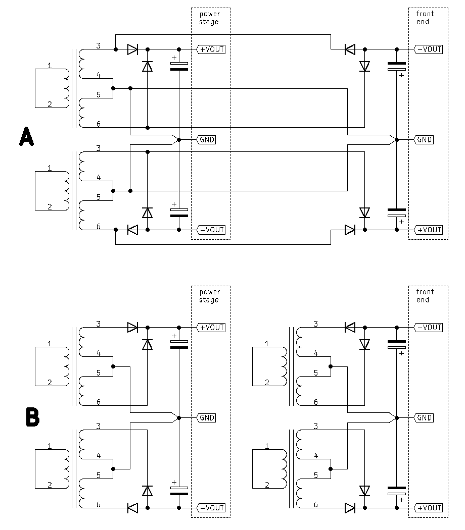
If Naim style rectification sounds better (than the usual full wave bridge): would that still be the case if another load would be connected as shown in my last diagram "A"?

(Of course provided the VA rating of the transformer covers the total load. And as you say the additional load could be a front end or another power stage - I just chose the former because of the easier GND arrangement.)
 
I’m no expert here of course, but if you combined your two A circuits into one, wouldn’t you then be using full bridge rectifiers on each side? So, you’d be back to the “normal” way of doing things?
 
From the view point of the transformer: yes! But from the view point of the load my "A" schematic would give me 2 independent Naim style supplies (with 50Hz pulses on each cap instead of the usual 100Hz). I wonder about the downsides though...
 
I’m afraid that’s not what I see. Combine the two, and both the transformer and the loads “see” the same as a conventional bridge rectifier circuit would provide. Yes, you’d get two independent supplies, but no, they wouldn’t be Naim style. Maybe you could combine them, to demonstrate what is different?
 
Yes, combining them would result in the usual bridge rectifier. Hence I wanted to ask about the version labelled "A"...
 
I think I noticed that in my Naim power amp a 300, they use multiple bridge rectifiers but only use half the diodes in each much as shown by the schematics listed in this tread, I was initially puzzled by this apparent waste but assume it’s for convenience of mounting and good heat sink connections of the full bridge rectifier packages?
 
Yes, that's what we've been talking about. A is a conventional bridge rectifier circuit. Please prove me wrong ;)

Oh, please check again the diagrams in the first post. Also did you notice that "A" has 4 secondary windings...?
 
Last edited:
I think I noticed that in my Naim power amp a 300, they use multiple bridge rectifiers but only use half the diodes in each much as shown by the schematics listed in this tread, I was initially puzzled by this apparent waste but assume it’s for convenience of mounting and good heat sink connections of the full bridge rectifier packages?
Exactly this. We used to replace dead stud rectifiers on very old NAP160/250s with this arrangement.
 
Being red/green colour blind is not especially uncommon. Would anyone care to amend the diagrams so that those of us with this common issue could actually understand the thing?
 
OK, I made B/W versions of the diagrams, hope everybody can read them better now. This is the first circuit from the first post, that's what I believe Naim used in the olive NAP250, hence I called it "Naim style rectifier" (here is the online simulation):

BU9qUC5.png


This is the second diagram from the first post (simulation):

ycZm8Uq.png


Now the two diagrams from post #37:

ALPLkyz.png


"A" is again the Naim style rectifier but with a second set of diodes / caps added (simulation): this other set is connected to the normally "unused" half of the AC wave (which Naim used only to power the front panel LED logo). So basically "A" would give me 2 Naim style supplies: when one gets charged the other one is diconnected (through the diodes) and vice versa, so I wonder if that has any downsides compared to "B"...?

In simulation all versions look almost identical to my amateur eyes. I still don't understand how one could sound better than the other - but I tried, and the difference was not small!
 
"A" is again the Naim style rectifier but with a second set of diodes / caps added (simulation): this other set is connected to the normally "unused" half of the AC wave (which Naim used only to power the front panel LED logo). So basically "A" would give me 2 Naim style supplies:
As explained above, I disagree. Please redraw A, so the diodes are next to each other, and the capacitors are above each other. Post the redraw here please. You will end up with two of the second circuit.
 
  • Like
Reactions: jpk
I wonder if there are two things in play here.
The 'Naim-style' rectification is as you say working at 50Hz charging pulses rather that 100Hz so maybe the 'reverse recovery spikes' being further apart contribute less noise and the harmonics may also be shifted down by an octave.
Also, with class A/B amps, the supplies are only loaded for the respective half-wave. Where you are using a standard bridge arrangement and a single transformer on a common core, perhaps the windings interact so loading on the plus rail transforms through to the negative rail and vice-versa.
 
  • Like
Reactions: jpk
redraw A, so the diodes are next to each other, and the capacitors are above each other. Post the redraw here please. You will end up with two of the second circuit.

Thanks for clarifying: but that's exactly the point - I dont understand why the second circuit is "worse" than the first...!
 
Thanks for clarifying: but that's exactly the point - I dont understand why the second circuit is "worse" than the first...!
No body does. We don't *know* if one is better than the other! Care to prove it?
 
As I said I tried it, the sound was different, and the difference was significant. For me that's enough of a proof, I trust my ears.

redraw A, so the diodes are next to each other, and the capacitors are above each other. Post the redraw here please. You will end up with two of the second circuit.

...except that positive and negative rails come from different transformers:

bHcrlvx.png
 
We're talking about double-ended +/0/- supplies though.
So was I

I built a pair on 135 clones and experimented with both types of full wave rectification and the transformer centre tap to the smoothers sounded best to me.


Pete
 
I still don't understand how one could sound better than the other - but I tried, and the difference was not small!
Could you please explain which of these four circuits you’ve built and compared?

You’ve drawn the first circuit with two transformers, but wouldn’t it work equally well with a single transformer, having two centre-tapped outputs? Naim uses a single transformer anyway.

...except that positive and negative rails come from different transformers
So you do need two transformers here then?


advertisement


Back
Top