advertisement


Naim power amp wire - board terminals/connectors

Andrew L Weekes

Reverse Engineer
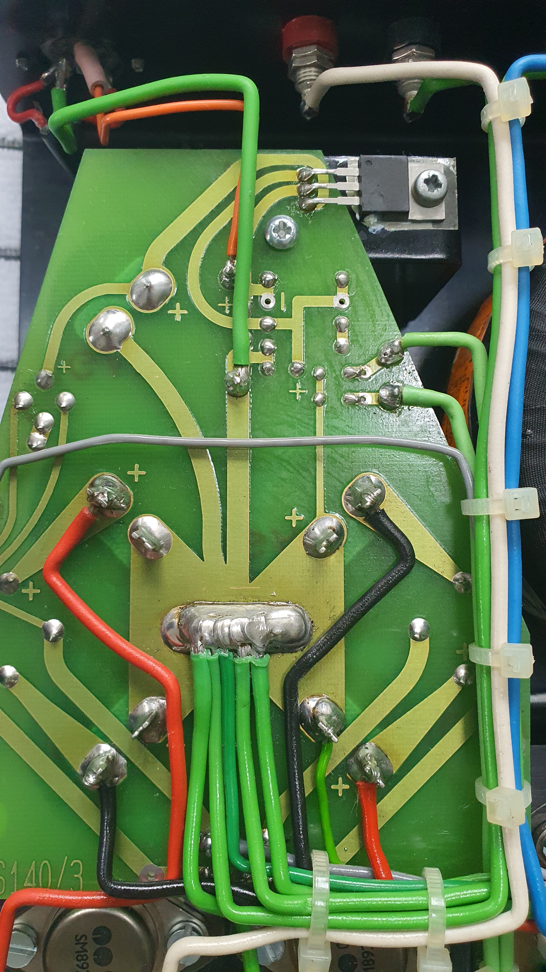
I'm modding an old NAP110 to a NAP140 currently and noticed that Naim seem to have wired them slightly differently over time.

NAP110's and some early units modified to NAP140's use the screened input cable as the signal earth to the power amp.

Later NAP140's and some modified ones have an additional substantial earth wire from the amp input to the 0V back at the PSU, although oddly this appears to create an earth loop, since the screened input cable is still earthed at the main DIN socket input.

Anyway, one of the currently spare terminals at the input is broken and I feel like they could all do with a refresh, given their age - does anyone know what the terminals/connectors are or any sources for them? I've only had a brief look but not found them yet. The alternative is to choose something better, these aren't the highest quality terminals I've seen, although clearly they're fairly reliable.

I can't get the main boards out at the moment as the screws are seized (I really dislike hex-head bolts, they round out so easily), but it makes sense to recap and service the unit whilst it's apart. The paste under the o/p devices looks really old and dried out.

AM-JKLVAbgEbL4_fLSHBBiE2j7Fh4d3uGlM91wL_lhShV5S3xwJb8bF-3jRwTQlA3R1DX1Y-3K-8WqBHxg3WdldMWBFMJpelwWbVU6eBQL--tOkyTKxLz6EMEGHXbM0D8hEj_nzE0YQ2uL-46sk9nofTYuhOrQ=w1431-h1073-no
AM-JKLWXqS7YEpR9ek-tPaNjL2JeAeDv80AzOYvMBtBV2uAWOvk7yLMV5JviqAQ_389X7i0rzNGgFKj17y5w1RMWp2tgYQp2AKLt_JbgoyQLHIPN0VaoBQU7_XIHrSZHuXPiwmqgs8OyScRZ0o8D65ztAQ1ZNA=w1431-h1073-no
 
Cannot help with the tags, but from a distant memory I don't think the rear thick green connection and front shield connection are 'joined' on the board?
So the thick green, is speaker output negative, 0 volts etc. The input of the amp gets its 0 volt connection back to the psu 0v line via the shield wire?
You need both and there is no loop.

You are right, but that's not what I'm referring to. I'll try and annotate a photo to show, but on some 140's there's a thick green at the input, and the screen of the signal cable. At the other end of the screened cable (where it connects to the DIN socket) there's an additional thin green that connects back to the PSU 0V creating a loop.

Edit: quick annotate on my tablet. I can see why the thin green is there; when a preamp is powered by the internal LM317, the preamp current would flow through the signal screen. As I'm not fitting the preamp supply, I'll remove the thin green and eliminate that loop:

AM-JKLWAD91ZJHA-1Jz0mm2xe8V73CCrtZVKuxR9gU9ojpg6oqugzLq-TcCLOB-efpVK9-H6_BaFWeeHZYSe5cG0CHJoSiVGcdEF1WQfVWvW3GLOsBnhKEtHwq75sApvjU5nKB1SMJ7bLgGHUx1bXYj0RSzhcw=w1000-h750-no
 
On the later psu boards, the green wires from the front of the board only connect to ground via small value capacitors on the psu board.

I think I read somewhere that on models like yours, the capacitors are under the black heat shrink at the psu end of the green cables.

If true, it would be easy enough to check with a meter when it's disconnected.
That might make more sense, for a company that focuses so closely on proper grounding, it did seem odd. Being a 110 my unit doesn't have the green wires at the input currently, so I'm unable to confirm, but I figure they were added for good reason by Naim. Might be one for some listening tests once I've finished rewiring to a 140
 
Interestingly this version makes it more obvious, the green wires (right hand side of board) are running through another component, wonder what value caps are used?

549e3e59c2d422c94310cbd671661d5fbf2ef3cd.jpeg
 
Interestingly this version makes it more obvious, the green wires (right hand side of board) are running through another component, wonder what value caps are used?
Yes they're tiny ceramic capacitors on my NAPS140/3 power board as above. If I disconnect the green wires from the amp boards and measure across the top with a meter, as shown in your picture, they're roughly about 50 to 100pF or so. That figure isn't terribly accurate, as I don't want to take things apart, but there certainly is no earth loop here. The signal wires therefore take 0V to the front end of the amp boards. The green wires go nearby via caps. The back end uses a different set of green wires.

Those white covers over the spade connectors makes removing them very difficult. I just cut off the plastic bits as they have no purpose other than looking nice until broken by a meddler.
 
wonder what value caps are used?

I've just checked on my old 140 and they are labelled 22pF.

Avon posted whilst I was checking this so this is just an update as to their value.

The 180 has a weirder arrangement than the 140 with no actual connection made between the front board "ground" cable and the PSU ground. They are just a couple of unterminated purple wires running parallel to the input cable - speculating: that might provide the necessary capacitance by proximity?
Thanks for that, that corroborates what I found here too, that they're 22pF:

https://pinkfishmedia.net/forum/threads/naps150-3-psu-board-in-nap140-pics.156423/

They're obviously just an additional RF ground.

The NAP180 arrangement is odd, but given the length of the wiring of it's probably just stray capacitance coupling to the signal shield. It's probably acting as a lumped element/transmission line filter. An open circuit transmission line is an effective short circuit at the opposite end at a frequency determined by it's capacitive and inductive reactance. It's common to make simple RF notch filters from lengths of coaxial cable this way.
 
Last edited:
Hi Andrew, speaking with Les W he said he will be able to help you in a couple of weeks if that is suitable perhaps you can contact him shortly.


advertisement


Back
Top