neonixcool
pfm Member
Good day
“Opium for people…”
Early NAP250 and NAP110 boards DIY
Julian Vereker boards design

“Opium for people…”
Early NAP250 and NAP110 boards DIY
Julian Vereker boards design
Good dayHello,
Nice work, its copy of original bords.
Regards
Ch
") )
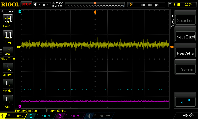
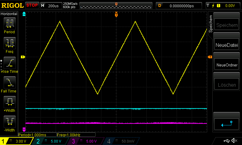
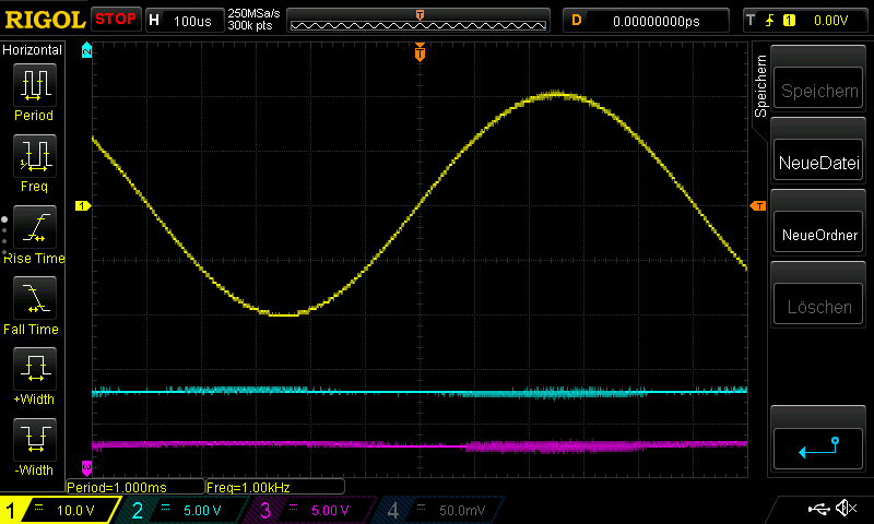
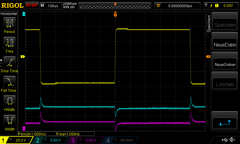
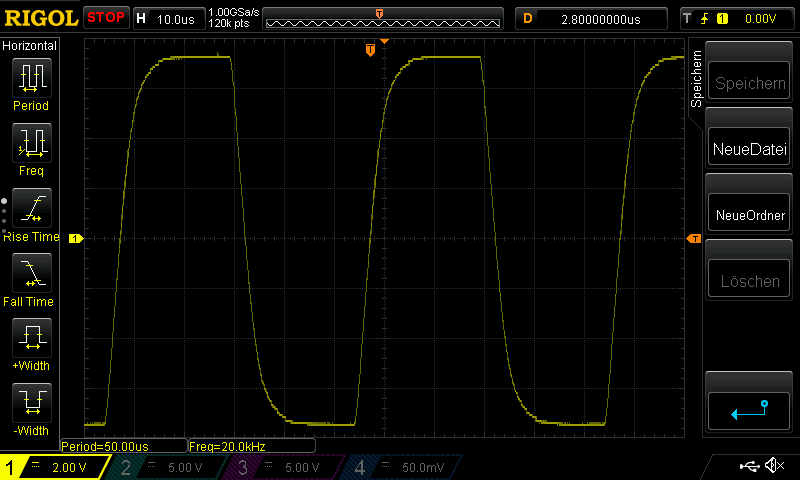
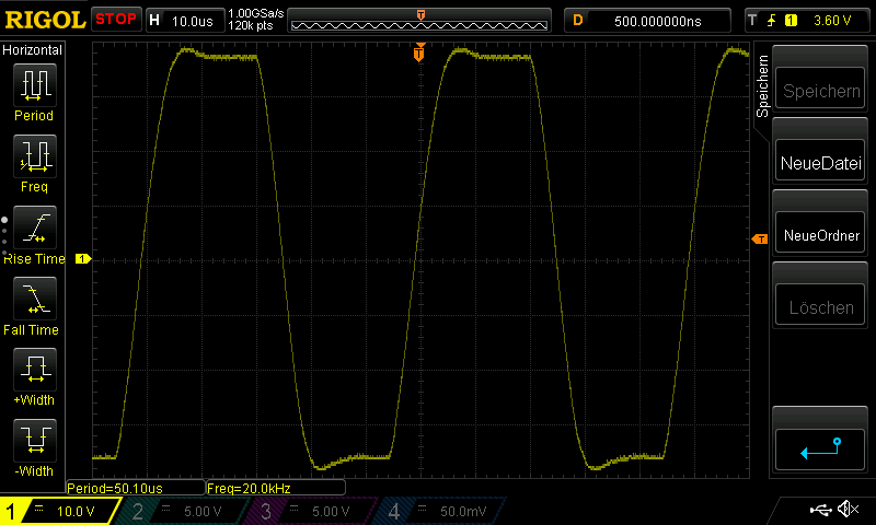
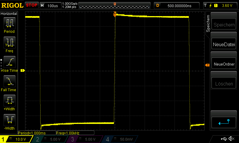
)You certainly need a test load, scope and signal generator [...] These checks are not rigorous, but offer some defence against gross problems. Defence against the dark arts anyone? Good luck.