advertisement


My NAP clone project

jpk

pfm Member
Hi,

with great help of forum members I managed to finally got my 2 power amps up running and wanted to share some pictures. I got original Naim boards for free from @stackowax and made an amp with them, using H+F transformers I found in the bay. My clone amp uses transformers by Toroidy and is based on the work by Jeff Young who also gave me a lot of advice here and on diyaudio. Rectifier and grounding schemes I did as discussed in the linked threads. With the help of @john.luckins and @timH I was able to make high voltage versions of the ALWSR regulator for the front end of my clone amp, see here. This is a picture of the amp with the original boards:

LzhVtZ2.jpeg


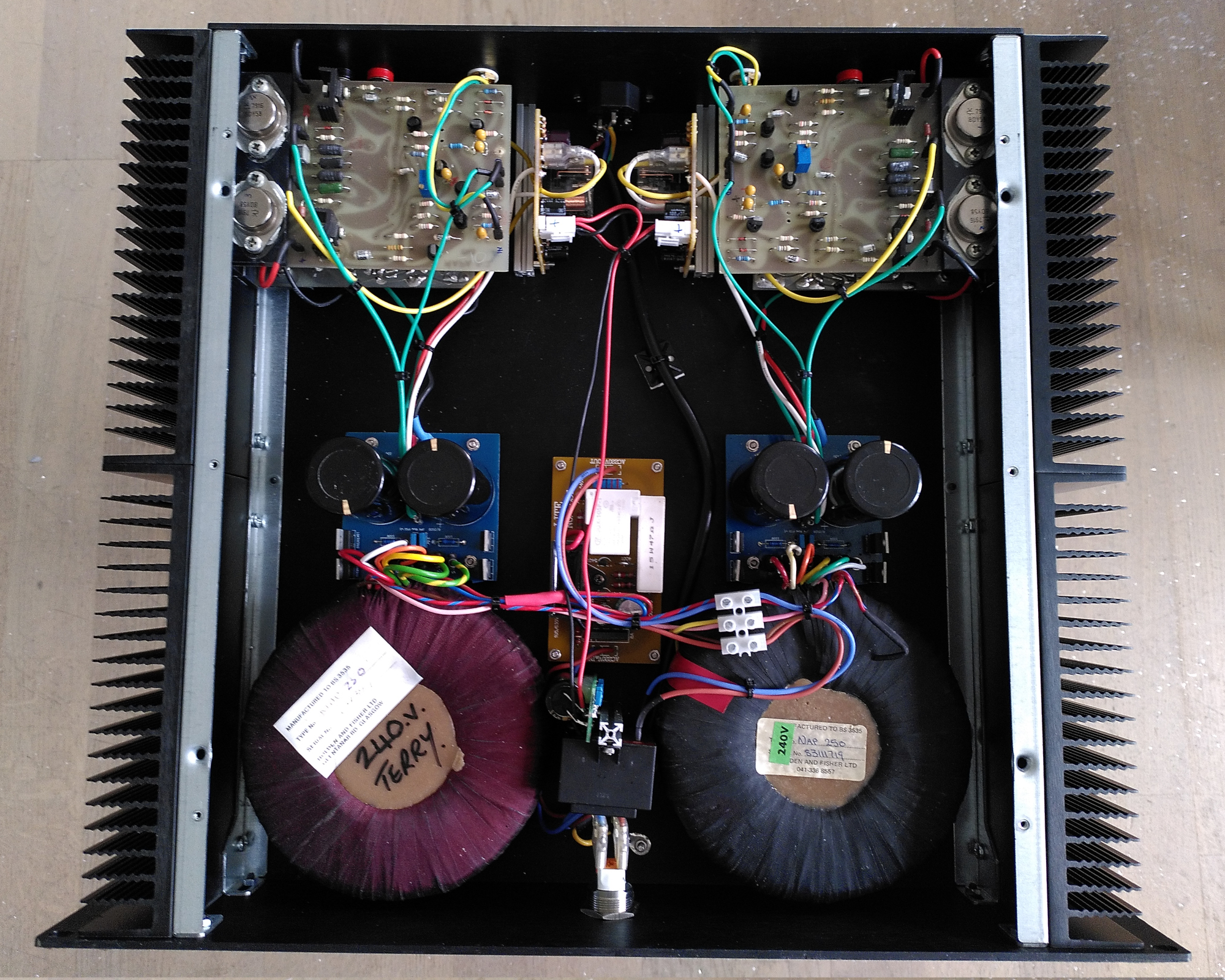
There are soft power on and speaker protection boards, the main caps are Mundorf, and it sounds great: round, punchy, natural, deep, transparent.

cCn5htK.jpeg


This is the clone: the third transformer in the middle has separate windings for each channel, so again 2 mono amps in one case. BTW both cases are Modushop 2U, and both amps have an extra small transformer to power the protection and soft power circuits. It sounds cleaner, more open, less cloudy, more natural, more transparent than the vintage amp, but also a bit flatter and more tiring - but I expect this to improve over time, it's running in for it's first day only (the vintage amp runs for weeks already).

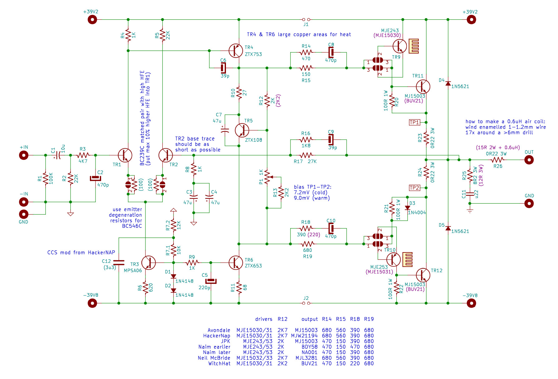
This is the psu schematic I used:

TQ2orb0.jpeg


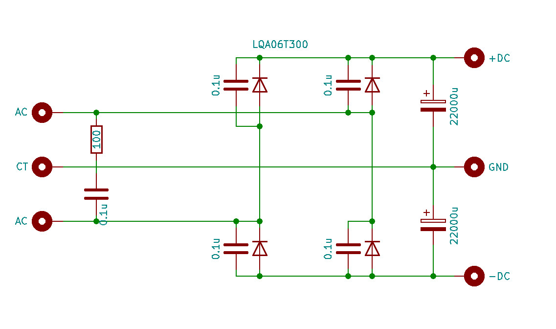
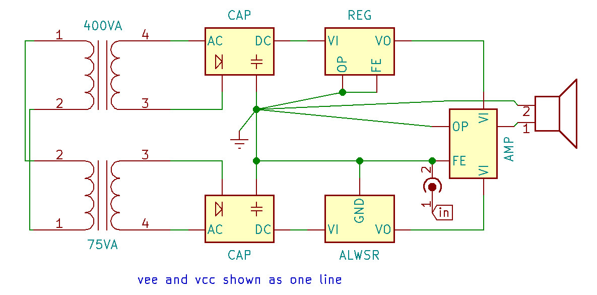
For the power stage I used 4x 10.000uF Kemet slit foil caps, for the front end 2x Mundorf 22.000uF per channel. The Mundorfs sound so much better on the front end than all other caps I tried including a CRC version. Both amps have BDY58s, I got mine brand new from Halfin who still had them in stock. This is how the grounding is wired:
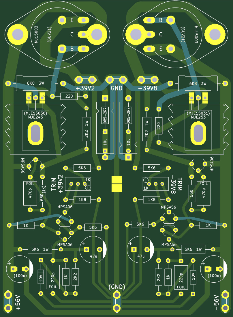
enMXbyG.jpeg


The amp board:

yRTQj1N.jpeg


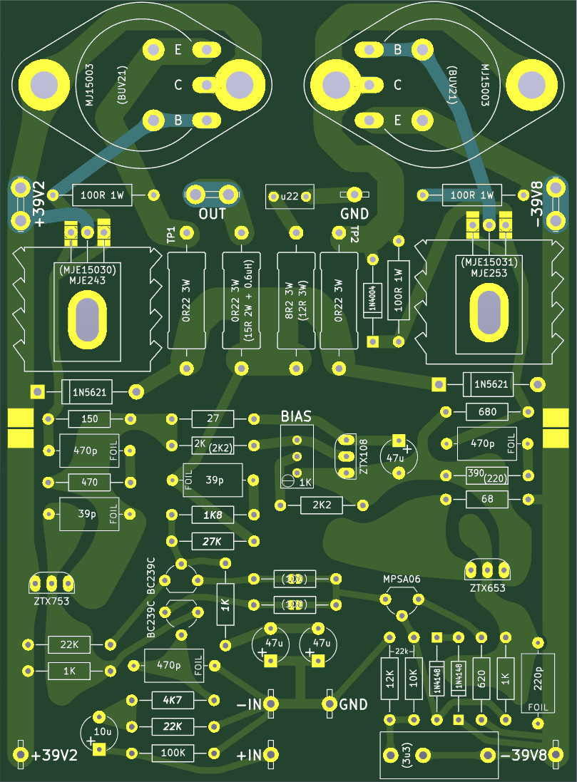
Is the grounding layout good around the input? The next picture shows the regulator board - as you can see I tried to make a star earthing layout, is that a stupid idea...?

qk6XUBd.jpeg


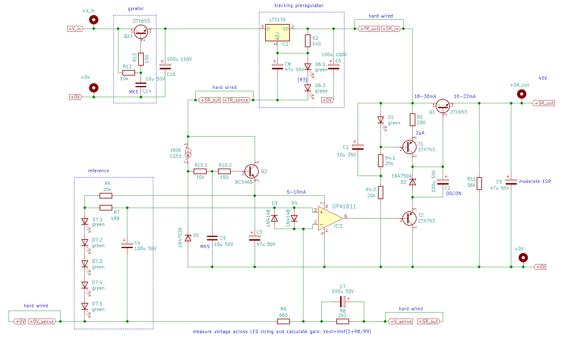
The high voltage ALWSR:

EDnr6Dl.jpeg


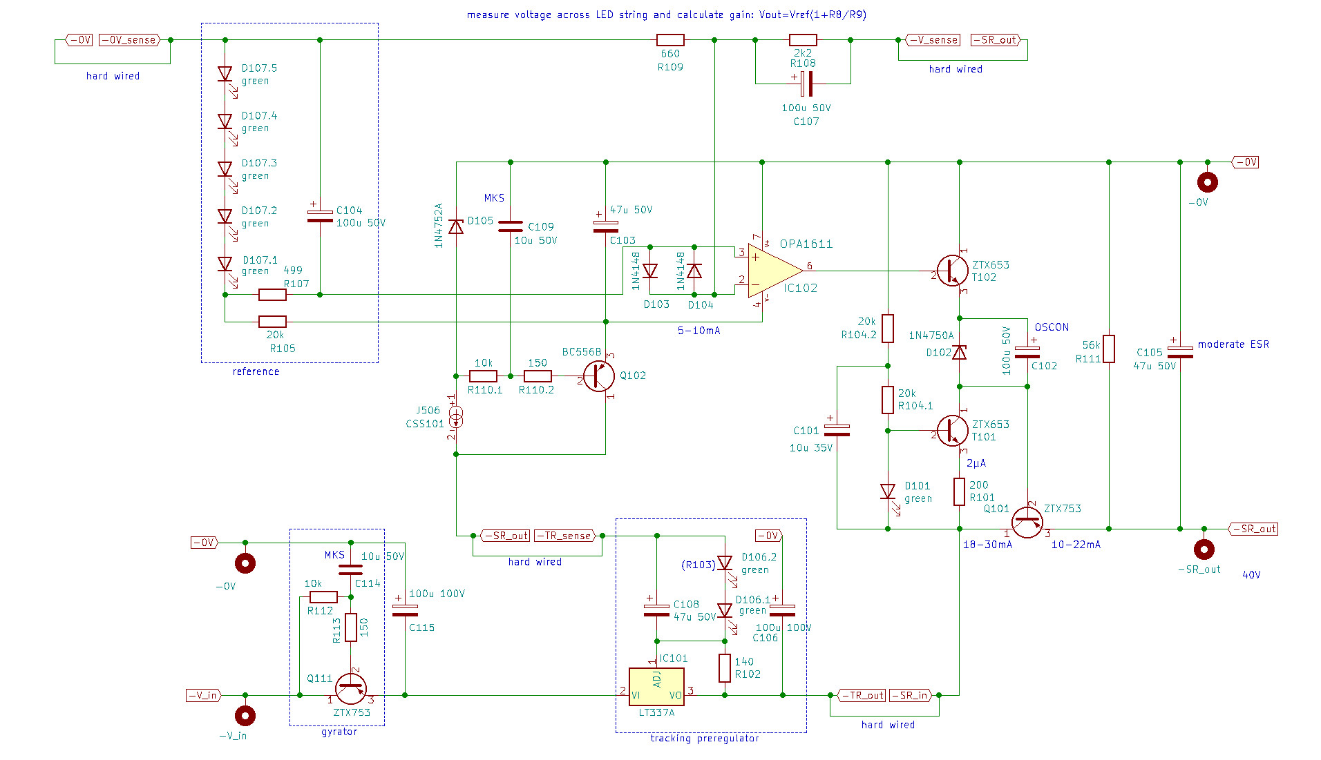
The negative version:

0Yl6QRs.jpeg


I am very happy about finishing the project, it was more work than expected... The cases are closed versions and needed modifications because the heat sinks were too long - I had to face them off a couple of millimeters which was not so easy, I finally did that on my lathe with a 50mm face mill.

I am happy with the sound, but would be glad to hear suggestions on how to improve from here. Many thanks all you guys for the help, and this is really a great forum that made it possible for me!
 
Could I ask, what made you decide to regulate the backend PSUs of the amp? Did you design the PCBs yourself and how did you optimise their layouts, especially with regard to ensuring stability and avoiding oscillation?
 
I wanted to know if it sounds different/better because I know from the original Naim amps that I prefer the regulated ones.

I draw the PCBs in Kicad but don't have the knowledge to take stability or oscillation into account (I am a hobby diyer). Do you think the Naim power amp circuit is prone to such problems in regard to the PCB layout?

It has some stability issues at the best of times, and there are things that could make it worse.

There are also some layout choices that make distortion and PSRR much worse if you get them wrong. Doug Self''s book is a good resource, and many of his points apply directly to the NAP (for example, where you take the feedback signal from, where to connect supply bypass caps and so on). Others are specific to his circuit.
 
what preamp are you using with yours clones of NAPs ?

I am working on a NAC clone, but since it's not completed yet I use my DAC to directly drive the NAP through a stepped relay attenuator. It works, but I hope the preamp will improve things. Why do you ask?

Doug Self''s book is a good resource, and many of his points apply directly to the NAP (for example, where you take the feedback signal from, where to connect supply bypass caps and so on).

I tried to understand and follow some of his suggestions, for example where feedback is taken from, and also the grounding scheme within the PCB, especially near the input. If you see mistakes in my layout please alert me!
 
That’s a good answer PD. But OK, you design the PCB using the correct rules, but you never really know how it will behave once built. As you do, it’s essential to have speaker protection included, but you also need to check that the current drawn by the circuit is as expected. To check for oscillation, the use of a high frequency oscilloscope (100MHz) at the output is essential I would have thought.

I’d tend to shy away from having to design such a PCB myself, so for example, I’d modify the original Naim one, to include front-end regulation etc. I could be wrong, but I feel the sound you get out of this thing will depend almost as much on the PCB layout as it will on the circuit itself. I was never sure why the Naim and Avondale boards don’t use star earthing. Maybe that’s just because the layout used gives more stability or better sound?

I therefore stick to preamp circuits myself. Power-amp stuff is a dark art.

I’ll get my wand …

You certainly need a test load, scope and signal generator. There is a PFM loan scope if you don't have your own.

I am not sure you need a 100MHz scope (the output device fT is not that high, so it is hard to have oscillations above about 10MHz), but checking behaviour on test loads is always a good idea before sacrificing a speaker. An 8(ish) ohm wire wound or thick film resistor is a sane test load. Wirewound will have a bit of inductance, but we do what we can. Ideally you should get a fairly high power one, so you can do at least short tests all the way up to clipping. One of these might be good investment for amp testing - https://uk.farnell.com/arcol/ap101-8r2-j-100ppm/res-8r2-5-100w-to-247-thick-film/dp/2530868

Square waves can be very informative - look for over shoots or ringing on the edges. The standard NAP circuit is unstable into small capacitor loads, as it lacks an output Zobel network. This is why you have to use specific types of loudspeaker cable with a NAP. I think large capacitances like 1uF across 8Ohms are OK, so they would be worth checking. The Avondale variant adds a Zobel network, and should be much more stable. The other thing to check is that if it goes into clipping, the recovery is clean - you don't want ringing or sticking. Unless you have a load rated for full power, make this a reasonably quick check. Regardless, don't burn your fingers on the test load, or let it set anything on fire.

Beyond testing that stability is OK, it would be nice to know that the distortion is not terrible. Ideally, you have a full measurement system that generates lots of graphs. Failing that, try a triangle wave at say 1kHz, and see if the output is linear. You will see gross distortion; I doubt you can eyeball 1%, but you would certainly see 10%. If there is a wrinkle round the zero crossing, the bias is set wrong.

The other thing to check is to wind the scope gain up, and look at the noise floor with no signal input. You should see white noise (AKA grass), with maybe a hint of 100Hz breakthrough. If this is more than about 1mV peak to peak, something is wrong.

These checks are not rigorous, but offer some defence against gross problems. Defence against the dark arts anyone?

Good luck.
 
Many thanks for the advice. I have a dummy load, a signal generator and a scope and will carry out the tests as soon as I am back home from tour and will report.
 
Hello JPK,

It's very good what you are doing.
If I may comment, it's very important to take your time, and especially to let the large filter capacitors break in for at least 2 months, before getting an idea of the overall sound of your amp..

Regards.
 
  • Like
Reactions: jpk
Thanks! Does it mean to have the amp on for 2 months, or does it have to play music for that time?
 
Thanks! Does it mean to have the amp on for 2 months, or does it have to play music for that time?
It just needs to be powered up, with no music playing, but people will disagree violently with that (ducks).

Could I please ask, do your circuit diagrams come from a simulator, such a Multisim, and are they available online?
 
  • Like
Reactions: jpk
Thanks for clarifying! I draw them by myself with Kicad, all schematics are in this thread (and the links I posted). Kicad files of Jeff's version you can find on diyaudio.com. If you need my files let me know, I can upload them to diyaudio and point a link to them from here.
 
Not really, just a BS-check,; not an invite to fight, at all.

Once the full working voltage is applied - the leakage current drops off really bloody quickly - this is also stuff documented in pfm-diy, by others, before. But then, I have a long memory ;)
 
  • Like
Reactions: jpk
Hello JPK,
Its better than play music.
only one month sound begin better, 2 months its perfect.
but you can stop all your systen during 1 to 3 days and replay music
its the better way........of course it depends on the auditory faculties of each and a perfectly regulated system

Regards.
Charles
 
  • Like
Reactions: jpk


advertisement


Back
Top