advertisement


Motorcycle Speedo - Circuit board cleanup / repair ?

-alan-

pfm Member
Not sure if this is the right subforum.. but..

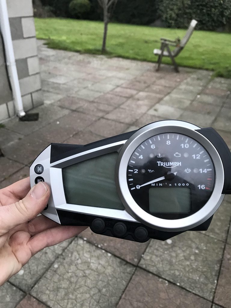
I have a Triumph Motorbike with an electronic speedo/instrumentation panel. You can do clever things on it like toggle menu buttons to access numerous functions and/or customise the main display(s).

Unfortunately, the buttons have stopped toggling (well, never did in my ownership), which is a bit of pain because the fuel level reporting function is buried somewhere in the inaccessible menus. A well known problem on the machine (675 Daytona) apparently.

I got a quot of 120 euro plus vat for a repair from a specialist repair tech place. Since I had to take the clocks out to bring it for repair, I thought I would have a look and see whether there were any obvious signs of trouble that I could potentially repair myself, and save the outlay.

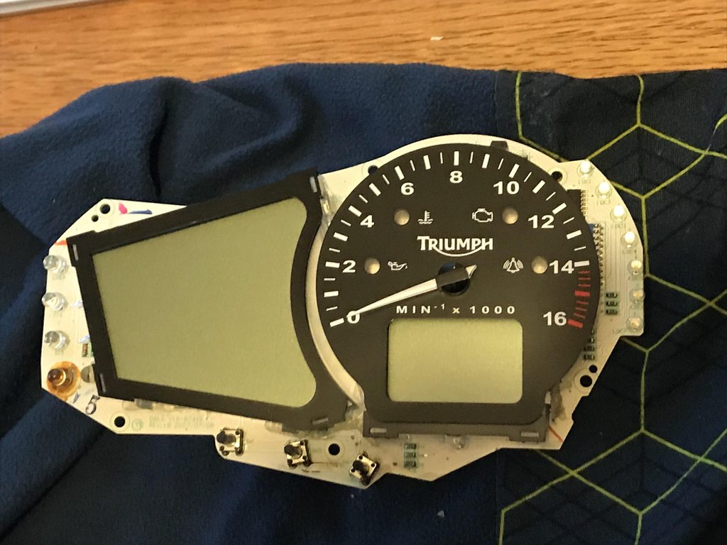
Managed to get the clocks open, and remove the main printed circuit board inside for a look. Took some pics to help get a closer look - and there do seem to be some signs of trouble. I was wondering if anybody could have a look at the pics and advise - which of the dodgy looking parts are likely to be reason for concern, and whether there is anything your average home hacker might be able to have a go at fixing without highly specialised tools and kit please ?

YqMU4llh.jpg


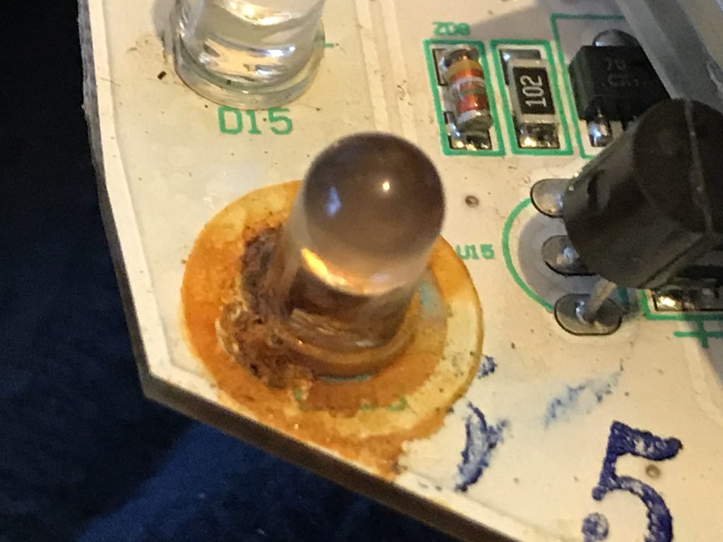
Front of the PCB and (what I thought at least were) some questionable looking components and circuitry:

aaWVXSbh.jpg


0uD4id4h.jpg


fY0teiVh.jpg


a1fUKyeh.jpg


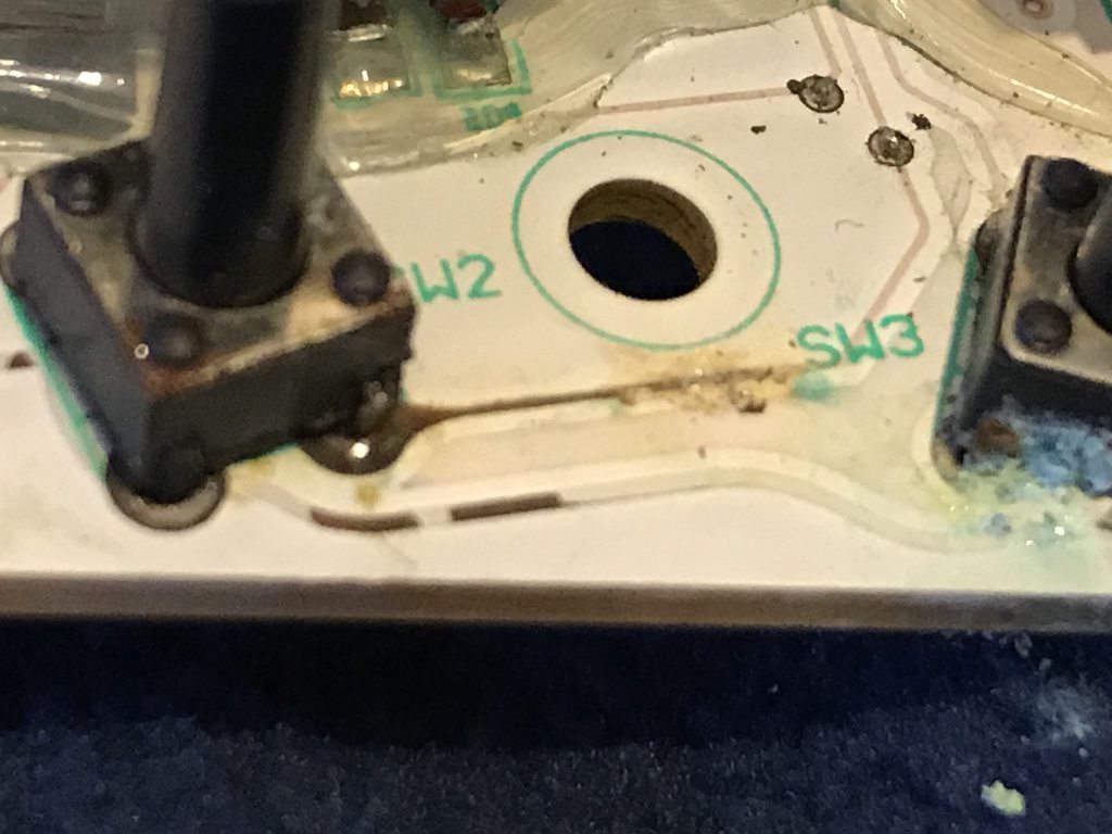
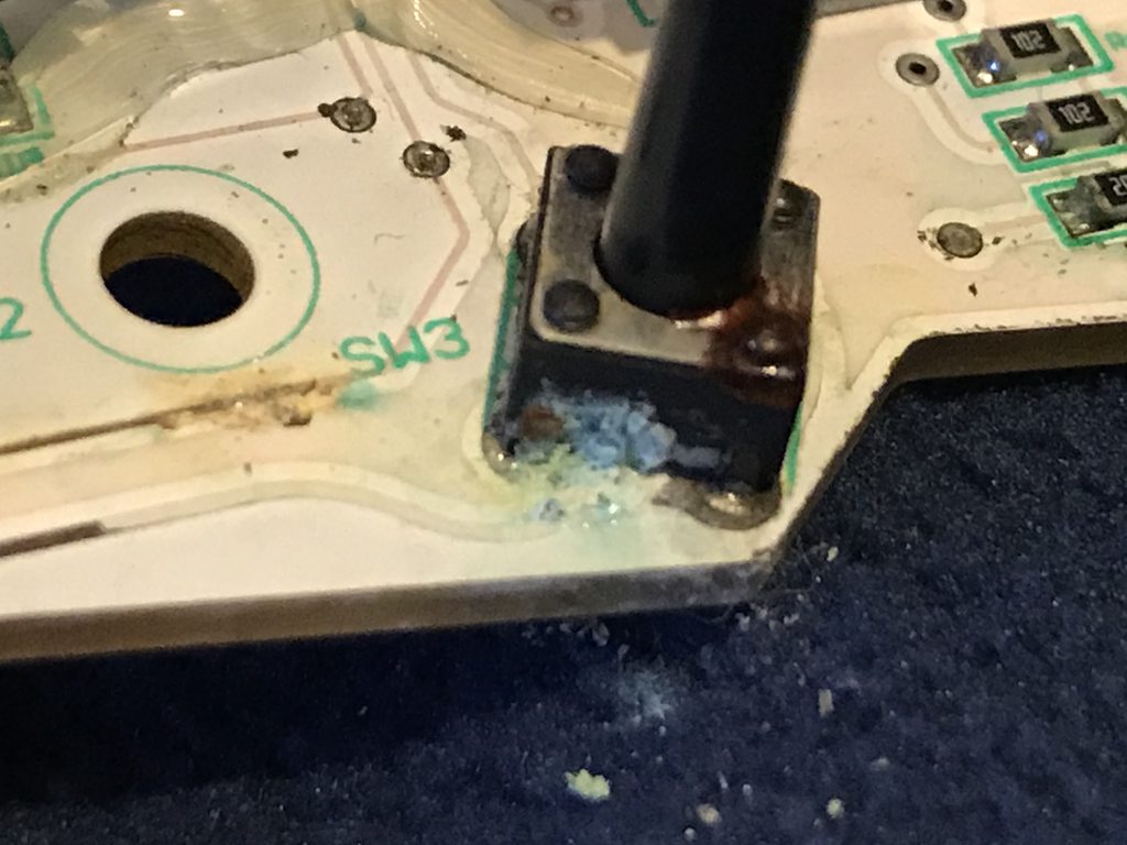
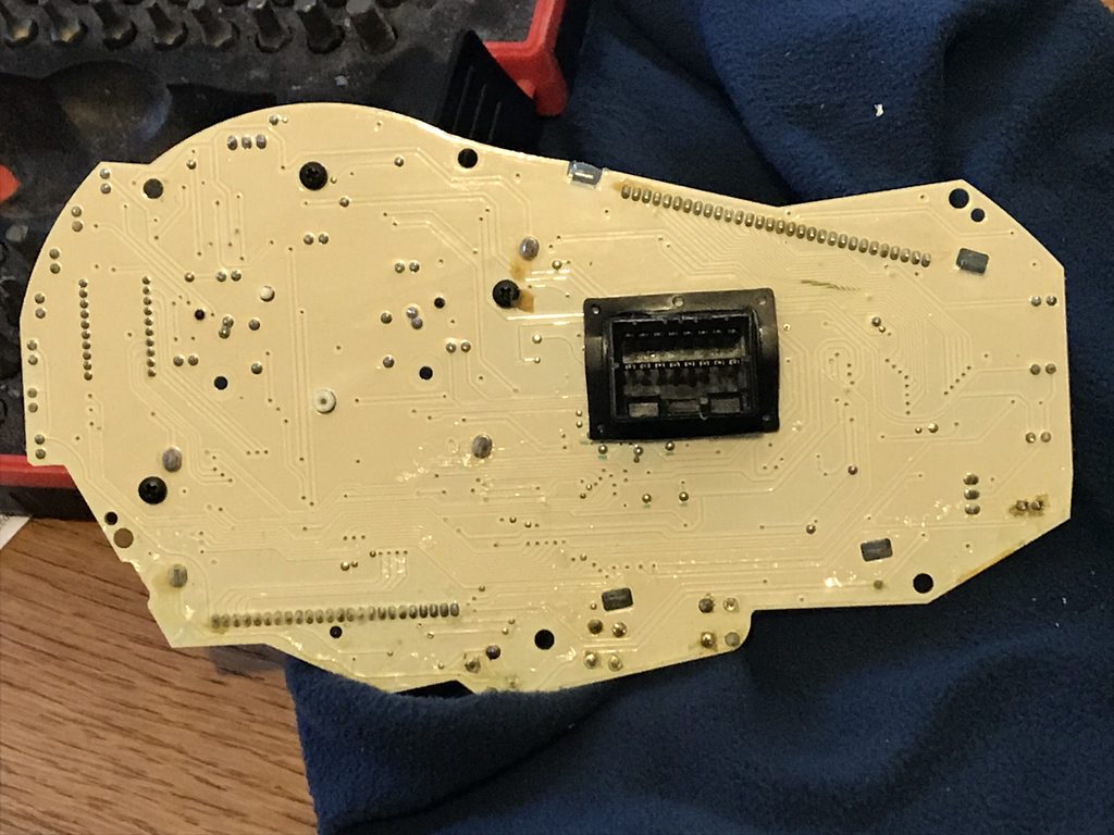
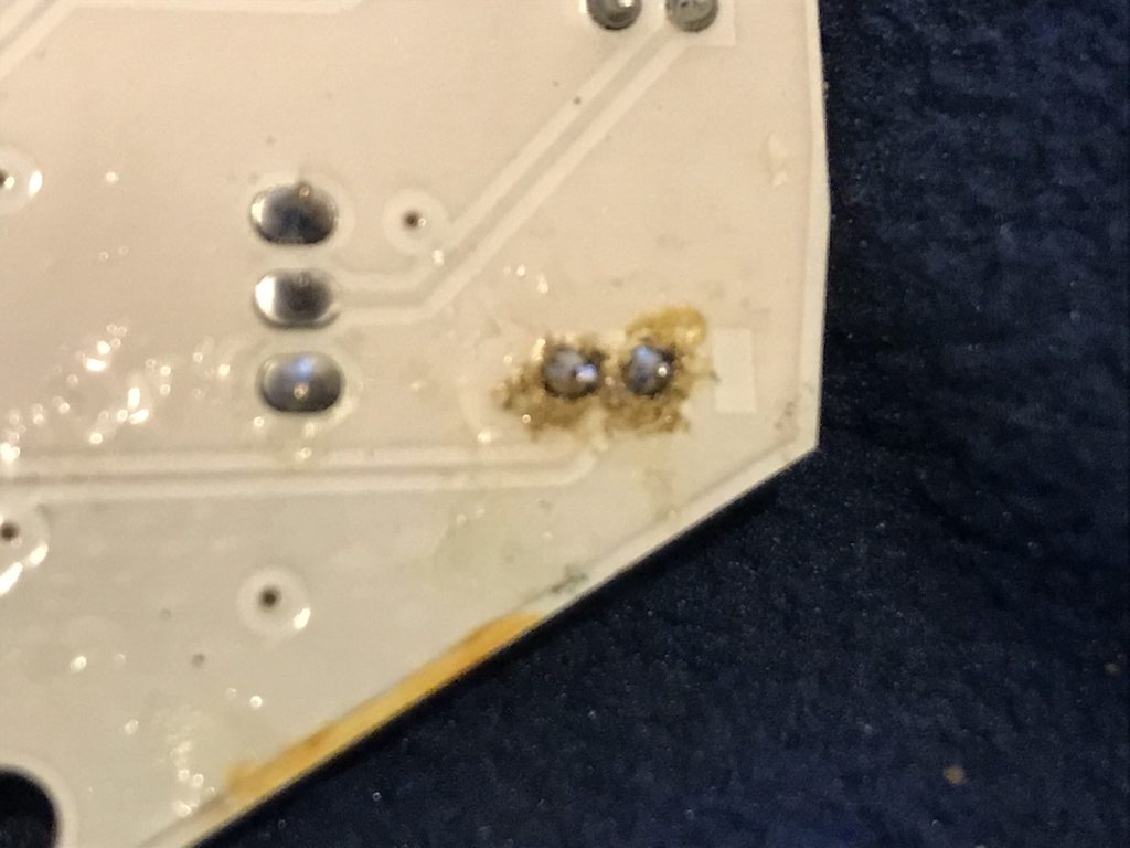
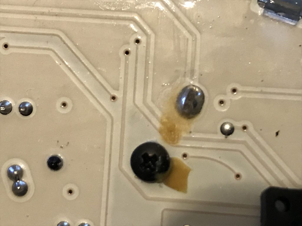
Rear of the PCB - and same, some of what I thought were dodgy bits:

lni3PTeh.jpg


as2RFQHh.jpg


raiaR16h.jpg


Apologies for the brain dump and image dump - but any info or advice greatly appreciated.

Thanks, Alan
 
Thanks Darmok.

Is the discolouration on the tracks between the two buttons labelled SW2 and SW3 likely to be a show-stopper ?
 
Personally, apart from the simple checks as above, I'd gently clean everything with something like an old tooth brush, and see what I could see. It does look like water damage in the pic's though.

If it is a common problem and there is nothing of help on the www, I would be inclined to think that you will be immensely lucky to achieve much yourself. If even moderately fiddly or complex fixes to this sort of thing are known, there are usualy countless YouTube videos and forum threads around telling you so, and the what the fixes are.

How old is the bike? If old enough, it could be the plague that car ECUs suffer as a consequence of a move to lead-free solder - metal fatigue giving dry joints. At least the fix to that is simple, if just that alone - reflow all joints.
 
Looks like water ingress has caused the problems, replace the switches and kynar any damaged tracks.

maybe a spray with conformal coating before putting it back together?
 
The bike is 10 years old, relatively low mileage - 15k miles - and doesnt seem to have spent too much of its life outside. The received wisdom is indeed that water ingress through through the rubber seals on the toggle switches is the most coming cause.

I think I'll give it a go with some of the recommendations above - little to lose really. So:

- source some replacement switches
- unsolder the old, replace with new
- general clean with a brush / (fibre pen/brush ?)

Can I ask - what does 'kynar the tracks' mean ..and.. what is 'conformal coating' ?
 
Conformal coating is a coating that encapsulates the whole thing (after you've done repairing it).
Kynar I am unfamiliar with, except that it is a polymer.

If you have a fine tip iron and the switch changes don't work, and you have the patience, you could try reflowing as many joints as possible. There are quite a few but not a huge number by the looks.
 
Thanks Darmok.

Is the discolouration on the tracks between the two buttons labelled SW2 and SW3 likely to be a show-stopper ?

Nooo, the push button switches are vunerable especially if they are outdoors in the atmosphere.

I have had to repair several lovely but expensive Technics SLP1200 top loading CD players with similar push buttons failed / collapsed switches.


If you can't find exact replacement push buttons, a daring techy could melt the plastic rivets and clean up the inside and / or replace the corroded contacts.

Be lucky.
 
Good on you wanting to have a go.

Simply check the PCB for continuity down the tracks and change (of even clean up the switches (with a cleaning spray)

I do this sort of stuff on 40 year old cars and cleaning stuff up makes a huge difference.
 
Last edited:
Thanks one and all btw.

Good on you wanting to have a go.

Simply check the PCB for continuity down the tracks and change (of even clean up the switches (with a cleaning spray)

I do this sort of stuff on 40 year old cars and cleaning stuff up make a huge difference.

A combination of blind ignorance and mule stubbornness largely Doc :)
It works, sometimes ..
 
There's not a thing wrong on the bottom, cream-coloured side of the pcb - so do not touch it.

The other, in the pics, shows a mix of corrosion, and also issues with left-over solder flux and water ingress.

The comment above about a toothbrush is the way first - use sim, dipped in some alcohol (isopropyl) and give all the discoloured areas a gentle and if needed repeated scrub. let the board dry well / repeat at will. Such de-natured alcohol will both remove flux residues, and - essentially - also dehydrate problem areas.

Do this two or three times if you like, it will not break anything further; then, when it suits you - plug back in again, see what remains wrong.

Whether or not this step is enough, you'll have a very much cleaner PCB for repair than at present, and it will help anyone who takes it on. HTH.
 
I regularly replace those type of switches in CD players. They're so cheap it's not worth messing about trying to revive them. Just put new ones in.
 
So..

Step 1. Cleaned the circuit board with a toothbrush, which seemed to remove a little of the dirt/corrosion round contacts.

Step 2. Applied some aerosol 'Electrical Contact Cleaner* ' from a can, and reapplied the toothbrush.

This seemed more effective, but also has caused a transparent plastic type coating to start to flake off across the board. I'm guessing this is one of the polymer coatings applied to the board to seal it as described above.

Is this bad, have I messed the flippin' thing up and ruined the board already ?

*According to the spec: "Contains: Naptha (petroleum), hydrotreated light. 30% Aliphatic hydrocarbons. Safe to use on metal, most surface coatings and plastics"
 
No; such a coating is solely intended to keep water out. It has no effect on the boards technical performance otherwise.

Unfortunately such stuff is equally adept trapping keeping water in ... if the coating has cracked or failed at any point (inevitable, but not irreversible)

Keep going, gently cleaning & drying, and don't worry about it. Fundamentally - as others above have commented - in individual issues this is simple stuff to resolve, even if as a whole right now - the unit looks a problem.
 
Thanks Martin :)

The second thing which has become immediately apparent is that at least one of the toggle switches must be replaced. I broke the stalk letting the weight of the board apply a bit of a bending moment to it :rolleyes:. I see they are indeed inexpensive and readily available on eBay.

Please forgive the numpty level question..but how does one remove and reconnect them: apply a soldering iron at the four contact points underneath and wait until it melts / remove / and then solder back in the same way ?
 
Thanks Martin :)

Please forgive the numpty level question..but how does one remove and reconnect them: apply a soldering iron at the four contact points underneath and wait until it melts / remove / and then solder back in the same way ?

No, you need a solder sucker or copper braid to remove the solder, try not to take too long or use a moderate powered soldering iron.

25 watt max, 15 watt should be enough.

Solder sucker...

https://www.amazon.co.uk/dp/B000LFTN4S/?tag=pinkfishmedia-21
 
This site contains affiliate links for which pink fish media may be compensated.
Understood, thanks.

And is that applied on the same side of the board as the switch, or on the other - or does it matter ?
 
Understood, thanks.

And is that applied on the same side of the board as the switch, or on the other - or does it matter ?

Desolder the soldered side contacts, don't dawdle cos you may inadvertently lift the pcb contact track if you overheat the pcb.

Good luck. ;)
 
https://pinkfishmedia.net/forum/threads/should-we-have-a-tool-tips-thread.245617/#post-4109213

HTH

:)

One other thought from experience - if in doubt, flat out works for soldering tasks, too: using a high-power iron for a short time will move/remove/make joints quickly with less collateral damage to parts & PCBs - than an under-powered one held in contact with a part& pcb forever in vain. that cooks both, but never has the oomph to adequately reach soldering temp insitu.

In the context of pics above, I'd suggest using a 25- 30w iron would be useful, not overkill.
I hope the many others here who do far more repair-work than I do, also pitch-in here... :)


advertisement


Back
Top