advertisement


LM117/317 datasheet tracking pre-regulator

13mh13

Pi-s Artist
In this diyaudio post, Martin noted "the tracking preregulator as shown in the old LM117 / 317 datasheet works really well where higher performance is required even for fixed voltage outputs."

For the datasheet tracking reg, does one compute Vout by appyling the standard formula to the 2nd LM317 -- also taking into account the extra Vref (so, a total of 2 x Vref) -- or is there a bit more to calculating Vout?
 
It's quite simple. You set-up the second 317 to provide the voltge you want, as normal. Then you pick voltage-setting resistors for the tracking pre-reg 317: R2= 2*R1 works well, keeping about 3.6v across the second 317.

Remember you get more total dropout, you need a raw supply at least 6v above your target output voltage for this to work. Add say 10uF ADJ pin decoupling cap across R2 for the tracking pre-reg, it improves performance quite a bit (not shown in the datasheet application diagram). Don't use a film cap /low-ESR type here though, it can lead to noise-peaking.
 
It's quite simple. You set-up the second 317 to provide the voltage you want, as normal. Then you pick voltage-setting resistors for the tracking pre-reg 317: R2= 2*R1 works well, keeping about 3.6v across the second 317.

Remember you get more total dropout, you need a raw supply at least 6v above your target output voltage for this to work. Add say 10uF ADJ pin decoupling cap across R2 for the tracking pre-reg, it improves performance quite a bit (not shown in the datasheet application diagram). Don't use a film cap /low-ESR type here though, it can lead to noise-peaking.

Thanks for your useful feedback! A few more follow-up Q's...

Do any of the resistors in datasheet pre-tracker need to be > 1/4 Watt?

I was looking over the heavy-duty version of your Flea and wondering: (a) how much an improvement it would be over the tweaked 317-based pre-tracker, as noted in this thread; and (b) how the 317-based pre-tracker compares with some of the simpler stuff on ALW's site (e.g. POOGE)?

My goal is to replace the 7815, 7915 and 7805 in a Philips CD650 (late-1980s CD player). The regs should be able to deliver ample power/current as I've noticed each of the stock regs in this CDP feed a lot of stuff: they all share a fairly large finned heat sink on the back of the CDP which really dissipates a "lot" of heat when the player is running -- if one of the stock regs is not firmly mounted on this heat-sink, it will go into thermal shutdown (not sure why Philips chose to "live on the edge” like this?).
 
1/4 w resistors are fine.

The fle just isn't suited for the kind of uses you are after by long shot - it's voltage-inefficient and can only supply tiny currents. The tracking-prereg 317 has similar supply line and load rejection to the POOGE circuit, a little more noise, but narrower bandwidth - its ability to maintain low output impedance falls off faster. On the other hand, its dead cheap, easy and with suitable heatsinking a 317 can deliver 1.5-2A all day long.

I wuldn't say Philips were 'living on the edge'. Remember some of the old chipsets drew a lot of current - eg SAA7220 digital filter, 5v at 200mA. A 317 can only dissipate c.1w without a heatsink before thermal shutdown (0.5w makes one too hot touch) If your player runs a reg for the digital filter from a 12v rail the regulator alone has to disspate a minimum 1.4w. That's quite a lot...
 
Martin/All:

Do you think there may be some performance (= audible?) gains by "upgrading" to LT1083 (3A) or LT1085 (5A) Low Dropout (LDO) regulators? They are quite a bit more $ than plain 'ol LM317s. I've heard that LDOs can actually be noisier than standard versions. But some DIYers note they may, after all, be superior.
 
LT1083 is actually 7.5A and LT1085 is 3A. The almost direct equivalent to the LM317 is the more affortable LT1086. Many have said it sounds better than the 317, and I don't remember anyone saying the converse. It does require a bigger cap on the output than the 317, but the Philips may already have something appropriate. You should check the data sheet.

As Martin has said for the 317, the LT108x family are not the ultimate. They are not really low dropout either, compared to Linear's LT1963 say.
 
Add say 10uF ADJ pin decoupling cap across R2 for the tracking pre-reg, it improves performance quite a bit (not shown in the datasheet application diagram). Don't use a film cap /low-ESR type here though, it can lead to noise-peaking.
So do you suggest a 10uF tantalum or electro? And, just to clarify, you mean R2, which in the datasheet is a 720-ohm resistor?
 
Afterthought: maybe I should explain why the ESR and size of this additional cap matters.

Look at the tracking pre-regulator diagram in the linked datasheet. Let's call our new cap across R2 'C3'. This creates a network R1C2,R2//C3 around an element with gain (the second LM317). That is, R1C2, R//C3 forms a Wien Bridge!

So we need to take care that 1) any tendency to oscillate is outside the audio band and 2) not to promote it by use of low-esr caps on the output of any reg.

For the given datasheet values, using 47uF for C3 pushes the potential 'peaking' down to below 18Hz, and I'd recommend this or larger (100uF of cheap electrolytic works well). This gurantees the thing won't actually ring, because the low output impedance of the 317 here damps things entirely. But try it with a 1uF film cap for C3 and you can get an observable peak round 600Hz-1Khz (depending on tolerances of other parts for values given).
 
Martin:

Thanks for the detailed reply! It looks like you have tweaked -- or at least played with -- this reg under the o'scope. I don't have one so I can't provide any feedback. But your analysis indicates that the non-ESR 10uF tant. is a good choice.

Going back to resistors, for the first LM317 (the pre-reg) you recommended "R2= 2*R1 works well, keeping about 3.6v across the second 317". The datasheet notes R1=240 and R2=720, so R2=3*R1. Is your recommendation based on tweaking?

(BTW: I haven't built the reg yet because I'm still tweaking the R and C values as per this discussion.)
 
Those R & C values aren't remotely critical, just use whatever will keep at least 3v across the second 317. The datasheet values are fine.

(and yes - discovering the accidental Wien bridge is based on hours of meddling and wondering why it measured better but sounded funny!)
 
From the datasheet can R2 and R4 be replaced by zeners from improved noise performance as well as an adj cap across R4(zener)?
 
Resurrecting this now-old thread, Martin noted...
Afterthought: maybe I should explain why the ESR and size of this additional cap matters.

Look at the tracking pre-regulator diagram in the linked datasheet. Let's call our new cap across R2 'C3'. This creates a network R1C2,R2//C3 around an element with gain (the second LM317). That is, R1C2, R//C3 forms a Wien Bridge!

So we need to take care that 1) any tendency to oscillate is outside the audio band and 2) not to promote it by use of low-esr caps on the output of any reg.

For the given datasheet values, using 47uF for C3 pushes the potential 'peaking' down to below 18Hz, and I'd recommend this or larger (100uF of cheap electrolytic works well). This gurantees the thing won't actually ring, because the low output impedance of the 317 here damps things entirely. But try it with a 1uF film cap for C3 and you can get an observable peak round 600Hz-1Khz (depending on tolerances of other parts for values given).
My trusty old Tek o'scope died a while back, so I can't test out some of the stuff you recommended -- sigh!
IAC, in your experience with the datasheet tracking pre-reg, I assume that 47uF (or higher) for C3 is a better value (overall) than the 10uF noted on the Acoustica page? (I just ran out of 10uF tants and, IAC, am having a hard time locating 10uF tants in higher than 20V -- my new app. is a +/- 30VDC regulator).

Speaking of tantalums (and totally shifting gears!), I know they are somewhat popular on this forum (and, IME, are used extensively in decent equipment like Naim and various PFM projects). However, some DIY "gurus" are quite critical of their use. Perhaps, selecting high-quality tantalums is the "key" to successful use. If so, any brands you/anyone recommend (e.g. what manuf. are those blue jobs ubiquitous in Naim?)?
 
In the following ckt, I inserted a "drop-in" tracking pre-reg module, replacing the single 317 or 337:
Promethius_d1psu.jpg

I left the voltage-set R's -- Rb/Ra and Rd/Rc -- in place, but removed the 22uF caps (since the pre-tracker uses 1uF). Here's the National datasheet pre-tracker again:
317-pre-tracker.jpg

The no-load measurements for both the 337 and 317 pre-trackers, however, were way worse than just a single (default) 317 or 337: output voltage increased to 37V (317 pre-tracker) and 39V (337 pre-tracker) -- up from a tight ~30V for both sides. Worse yet, AC ripple increased on the 317 (~1.2mV --> 4.3mV) and the 337 (~1.2mV --> 6.2 to 10mV and fluctuating at that!).
The only thing I can see that may affect output is R3, the 120-ohm resistor on the output of the National pre-tracker. Dunno if that's tailored for that ckt? In the orig. +/-30V PSU, that R is 240 ohm.
Any other clues as to what may be the culprit?
P.S. Although I've built this ckt several times, and with good success, this is the first time I've dropped one in into a pre-existing single 3x7 position.
 
What's the raw DC voltage at the reservoir caps? I think you've just run out of 'drop out' headroom. If the pre-reg 'drops out', then R2 acts as a sneaky path around the secodnd reg, which will worsen ripple and noise... it links the raw side to the output.

The tracking pre-reg, esp as shown in the datasheet, needs extra dropout voltage. The daasheet values are set-up to hold about 5v across the second regulator, and the prerege itself needs a min. of 3v dc across it, so your raw supply must be at least 8v above the required output voltage. Looking at your circuit that could be a bit marginal.

You could try reducing the voltage set across reg 2, by reducing R2 from 720 to maybe 240R. You will still need a minimum of ~6v between input voltage and output for reliable operation. Drop the output voltage slightly if you need to.
 
What's the raw DC voltage at the reservoir caps? I think you've just run out of 'drop out' headroom. If the pre-reg 'drops out', then R2 acts as a sneaky path around the second reg, which will worsen ripple and noise... it links the raw side to the output.
About 41VDC, which should be plenty.
The tracking pre-reg, esp as shown in the datasheet, needs extra dropout voltage. The datasheet values are set-up to hold about 5v across the second regulator, and the pre-reg itself needs a min. of 3v dc across it, so your raw supply must be at least 8v above the required output voltage. Looking at your circuit that could be a bit marginal.

You could try reducing the voltage set across reg 2, by reducing R2 from 720 to maybe 240R. You will still need a minimum of ~6v between input voltage and output for reliable operation. Drop the output voltage slightly if you need to.
I'll get to some of these tweaks in a bit (away from home at the moment)...
Anyway, your advice about just how much extra voltage the pre-tracker may need makes me wonder whether the other pre-trackers I've got in my PS box were/are optimized -- indeed, several of them do not have as much voltage overhead as the problematic ckt above. The other "successful" implementations are replacements for 78xx or 79xx's, in which I compared output ripple and subjective SQ -- both of which were improved. Either the 78xx/79xx's are that bad or there's some other factor affecting the above ckt. All that said, and FWIW, the output ripple of the orig. (non-pre-tracker above) is the best of all the half dozen or so regs in my PS box.
 
The tracking pre-reg, esp as shown in the datasheet, needs extra dropout voltage. The datasheet values are set-up to hold about 5v across the second regulator, and the prerege itself needs a min. of 3v dc across it, so your raw supply must be at least 8v above the required output voltage. Looking at your circuit that could be a bit marginal.

You could try reducing the voltage set across reg 2, by reducing R2 from 720 to maybe 240R. You will still need a minimum of ~6v between input voltage and output for reliable operation. Drop the output voltage slightly if you need to.
Martin: One thing I've noticed is that "extra" overhead gets these regs (3x7, etc.) running warm/hot, even with heatsinks. And this applies to low-current demands as well.
In the tracking pre-reg example, then, why do two "cascaded" regs -- each with dropout voltage of 1.25V -- need "so much" overhead?
Speaking of overhead and heat, do regs like LM3x7 perform better when slightly "over-driven"?
(P.S. still planning on trying out your above suggestion -- when I have some time!)
 
timH:
Interesting...Some questions:
Do R1 -> R4 retain their National datasheet values for the published tracking pre-reg -- i.e., R1=240, R2=720, R3=120, R4=1K (variable)?
Can you provide some component values for voltages for which you have tested this topology?
How does it measure/perform compared to orig. tracking pre-reg?
Thx!
 
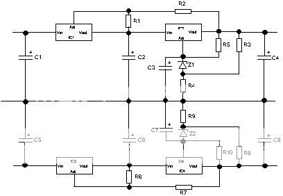
Here are the calcs

V1out=1.25*(1+(R2/R1))
R1=R6 1200
R2=R7 2700
V1out is 4.0625 V


V2out=(Vz+1.25)(1+R4/R3)+1.25(R4/R5)

Vz= 6.9 V
R3=R8 620 Ohms
R4=R9 2200 Ohms
R5=R10 1000 Ohms
V2out is 39.81935 V

These values are for use in a naim power amp which is where I have used the circuit to power the VAS part of the amp board. Voltage in is about 56v

I don't know how it performs compared to straight tracking pre-reg since I've only ever used this circuit. There's some stuff about the use of a voltage reference on the Neil McBride website. All I can say about performance is that I've loved what my McB clones do ever since I made them. Although I'm intrigued as to the difference a teddyregged front end might sound :)

Tim

ps I can't claim to be the developer of this circuit - that was done by two members of the forum (AshleyD and Fretless Eric) I just followed in their footsteps


advertisement


Back
Top