
You are using an out of date browser. It may not display this or other websites correctly.
You should upgrade or use an alternative browser.
You should upgrade or use an alternative browser.
Krell KRS-2
- Thread starter earthfield
- Start date
MLAS
Member
This is the update/repair I did in 2010/11:
https://drive.google.com/file/d/1xDU4Gj40R8P2pd78W10GM0705OyNf5WM/view?usp=sharing
https://drive.google.com/file/d/1xDU4Gj40R8P2pd78W10GM0705OyNf5WM/view?usp=sharing
Ton Amsterdam
New Member
Hi earthfield I love this threat and bought a KRS-balanced recently in Europe. I only can find the manual of the ‘normal’ version, the unbalanced, and have difficulties in finding the right cables (double RCA-single XLR). I appreciate your solution, and the manual posted in this threat seems to be the unbalanced version? Thank you so much for your help, regards Ton
earthfield
earthfield
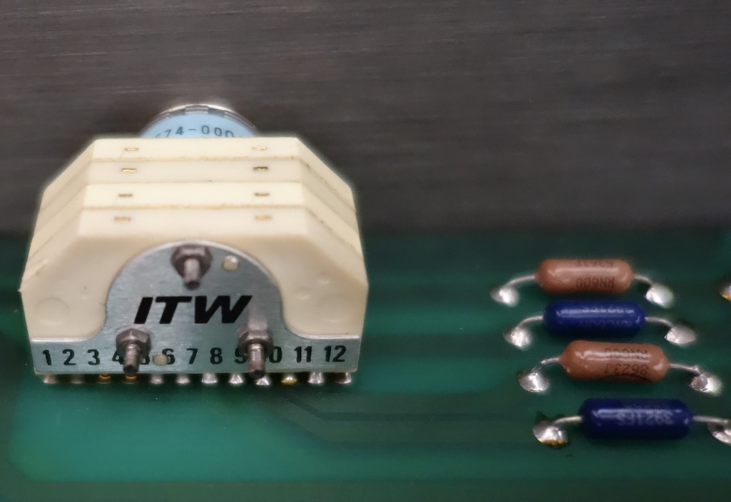
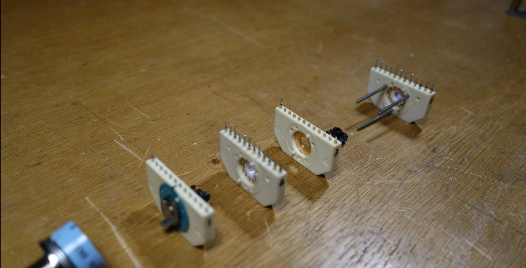
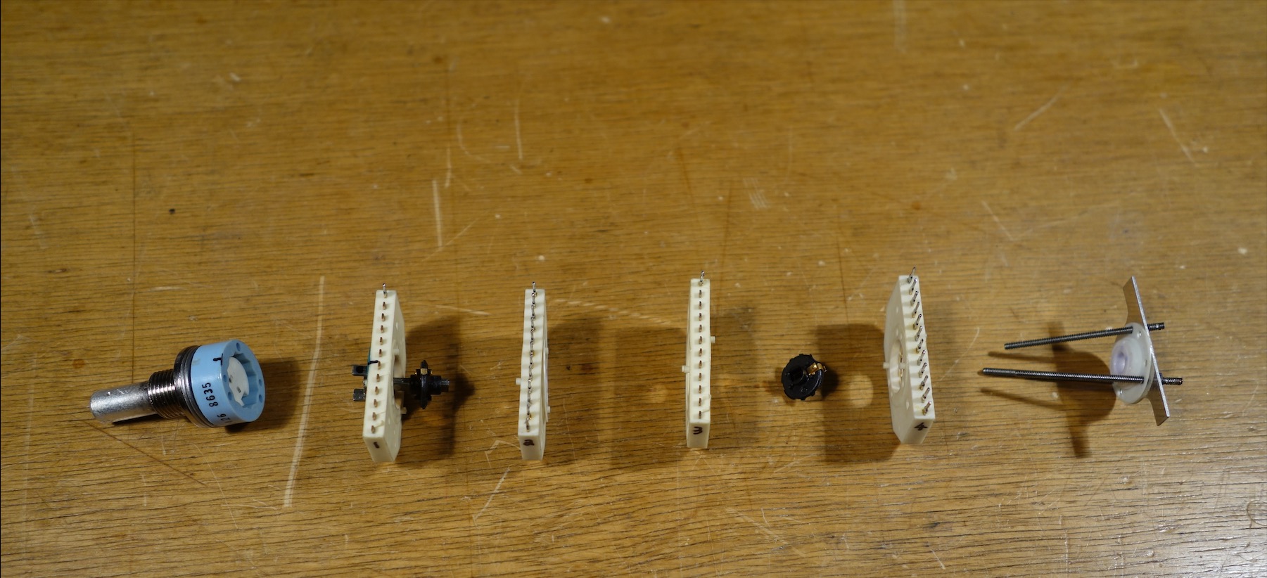
Strip and reassembly of ITW rotary selector switches.
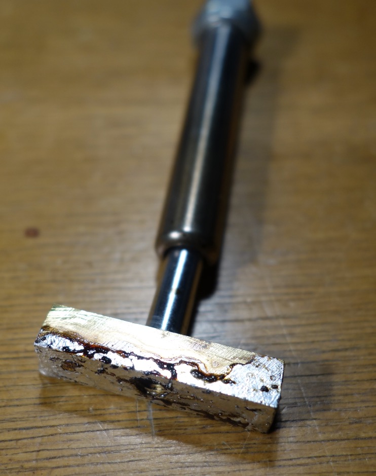
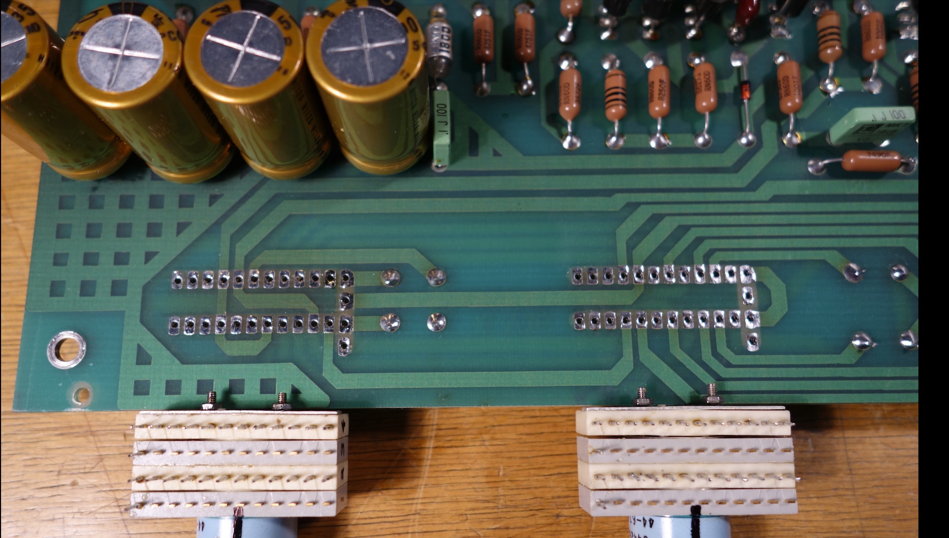
The double sided PCB required a new desoldering head solution.
Best solution I’ve found for desoldering double rows of pins on PCB’s…
Weller Soldering tips and nozzles for TCP/ S have changeable heads.
Weller DIL24 desoldering head 5 41 738 99, probably designed for IC's is no longer obtainable.
A weller DIL 16 assembly has a threaded head, cutting a piece of brass to within dimensions of the double row pin array and threading this allows interchangeability with the existing Weller TCP-s system.
It worked well.
The selectors are well made and serviceable, but had failed due to no thread lock glue being used in the front shaft plate and over the years came loose.
Tiny mechanics and many rotationally and orientationally specific parts require careful disassembly. Marking a line on the exterior is one simple part of keeping the rotational aspects good, dismantling from the name plate side is the best sequence. The pale blue part houses a sprung double ball and will easily ping out. The contact planes are a versatile integral design. Phosphoric Acid was used to clean these, then washed with pure alcohol, then a minute touch of Vaseline will keep 'em good for the years ahead. Reassembly with thread locker keeps it solid, don't tighten the planes till they bend, just a gentle compression. Some neutral silicone free goo was packed into the ball spring mech.
Feels solid and reliable again.
The balance/ attenuator resistors were also desoldered and fresh, quality silver soldered.
Most surprising was the sonic improvement that occurred, with an increase in sound stage solidity, width and clarity.
Last edited:
earthfield
earthfield
Hi earthfield I love this thread and bought a KRS-balanced recently in Europe. I only can find the manual of the ‘normal’ version, the unbalanced, and have difficulties in finding the right cables (double RCA-single XLR). I appreciate your solution, and the manual posted in this thread seems to be the unbalanced version? Thank you so much for your help, regards Ton
The manual on this thread is for the KRS-2 unbalanced, 'two chassis', it's really a three chassis, however it is directly coupled from source to output. IMO there is too much exotica in the cable arena, find the best gold plated Neutrik XLR's and wire them so you can 'lift the earth' by switch or touching a wire to make the first match with your equipment, everything must be at very low or no volume as this is a 'live' test which can be damaging if the mismatch is unusual, this is why the decoupling capacitor is in many hifi separates and consequently transformers on pro audio studio, who knows what earth you are connecting to, or what loops may be present. Sometimes having a decoupling capacitor integral to the cable. Plugs must be pulled instantly when you are hardwire testing. You are listening for mains buzz and eliminating it, I don't recommend it if you're not experienced. IMO System matching is one of the most underrated aspects of mating different hifi separates. Every manufacturer will ultimately use different integration/ parameters/ topology for their whole 'system'. Make sure everything is in phase, then there is of course two ways of viewing making the bal/unbal or unbal to bal cables or 'breaking them out'. Follow pro audio wiring guidelines.
To quote a well known review of the preamp range when it was released in 1987:
Krell's flagship preamplifier is the dual mono, four-chassis KRS-1A, available in conventional unbalanced form, or completely balanced.
The two-chassis KRS-2 represents designer Dan D'Agostino's assault on the real-world preamplifier market, but with many features in common with the cost-no-object KRS-1A. For example, the KRS-2, like the KRS-1A, is direct-coupled throughout. It does not have to rely on finding the world's best-sounding capacitors—it simply eliminates them.
Last edited:
earthfield
earthfield
https://farm8.staticflickr.com/7121/7010750061_2cd01d8b2e_b.jpg
sq225917, on the picture I can see the transistor 2SK147, could you tell me what the transistor is called next to in a low housing?
I've tried your link a number of times, but this is the first time it's worked!
That is not the same device in this thread, nor are any of the transistors you mention within the KRS-2, nor are there any long packages. Its completely different.
earthfield
earthfield
There are two stages of regulators in this pre amp chassis;
2x VN0206N5
2x VP0206N5
4x MJE15030G
4 xMJE15031G
Are there current low noise superior 'drop in' replacements that can be recommend for this circuit?
The same regulators are in the Power smoothing Chassis;,
4 x MJE15030G
4 x MJE15031G
Two of these are are running hot enough that touching them for more than one second burns, which doesn't seem right.
The outputs -under load- have voltages within 0.6-0.7V difference one ' rail' to the other. Full variance is from 23.6v to 25.3V.
I followed the change to 240V and the fuse changes exactly as Krell advised.
We have had voltages of 250V during the lockdown and the only difference between then (1987) and now is a huge increase in High Frequency square waves through mains power along with all the other unpleasantries of Switchmode PSU's putting tremendous noise through the power system and an apparent higher voltage.
Should I put current compensating inductors and all the usual mains power protection prior to the Toroid chassis?
Input welcomed...
PigletsDad
My intelligence test came back negative.
These part numbers are transistors, not monolithic regulators. The MJE are bipolars, the V(NP) are power FETs. I expect they are the pass devices of discrete circuit regulators. Don't fiddle, unless you are Dan D'Agostini you are unlikely to make it better. If running hot, add a little clip on heat sink on the tab.
With dual regulation, I would want measurement evidence that the mains noise was getting in to the audio circuits before changing things. If something is not broken, don't fix it.
With dual regulation, I would want measurement evidence that the mains noise was getting in to the audio circuits before changing things. If something is not broken, don't fix it.
earthfield
earthfield
Mains Voltage is running at 244VAC
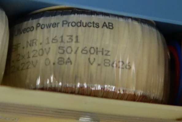
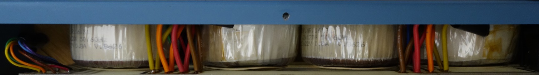
The Toroids are rated at 240V (2x 120) out to 2 x 22V totalling 384VA,
the eight outputs are all 17VAC within 0.1V under load. The voltage switch is 115v/230V.
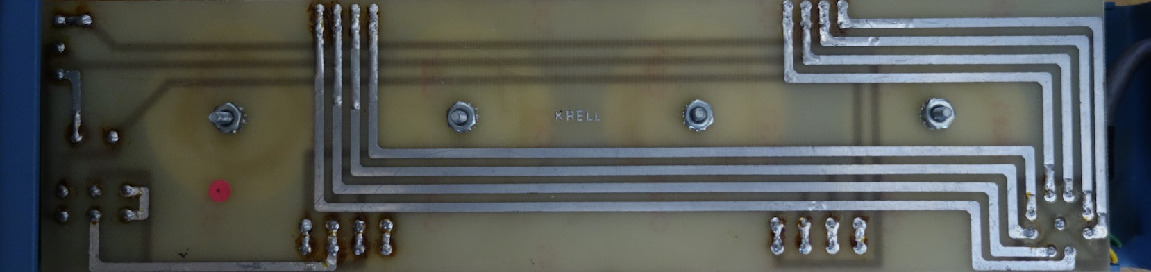
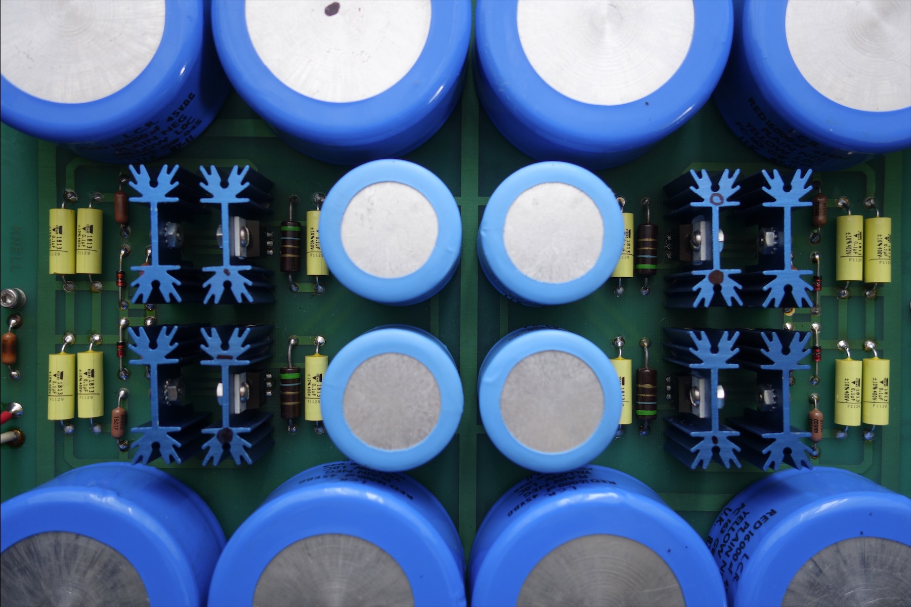
In the Power smoothing Chassis image, the ones running hotter are marked 0 and 1, respectively MJE15030G MJE15031G :-
Very little head room to add to heatsink, only a 1/4"; 6mm height increase.
Max permissible heatsink size increase to:- H= 36mm x W 40MM x 18MM.
On arrival to the Preamp chassis it's clearly engineered to output two dual rails of 24VDC however with the heat imbalance, within either 'rail' there is a 1 - 1.2v difference and between rails there is a 0.6 - 0.7 V difference, not much but i would expect this to be spot on 24VDC given the over engineering.
Krell suggests/says:-
" Minor power supply variations are tolerated because of the servo circuits in each section or stage. Since the circuits you describe are using discrete transistors (as opposed to regulator IC's like 7818 or 7918) if you wish, you can replace the zener diodes with "matched" devices to obtain closer voltage tolerances."
and
"There are a number of our products that were designed long ago, with some transistors operating at levels sufficient to cause high temperatures. If the original transistors in the device are operating too hot, and space permits, add a small heat sink to them."
I think we are talking about the 1N4750's in the above image.
Will update when the pieces come together, preferably from Krells archive...
On another note:-
To quote from another post from 2006...
Also those obsolete VN0210N5 and VPO210N5 devices only operate at about 3 mils so good subs are Zetex ZVP3310 and ZVN3310 and they are readily available and dirt cheap"
Not having experience with vertical DMOS power FET's,
has anyone else experience in such an application and can advise please?
The Toroids are rated at 240V (2x 120) out to 2 x 22V totalling 384VA,
the eight outputs are all 17VAC within 0.1V under load. The voltage switch is 115v/230V.
In the Power smoothing Chassis image, the ones running hotter are marked 0 and 1, respectively MJE15030G MJE15031G :-
Very little head room to add to heatsink, only a 1/4"; 6mm height increase.
Max permissible heatsink size increase to:- H= 36mm x W 40MM x 18MM.
On arrival to the Preamp chassis it's clearly engineered to output two dual rails of 24VDC however with the heat imbalance, within either 'rail' there is a 1 - 1.2v difference and between rails there is a 0.6 - 0.7 V difference, not much but i would expect this to be spot on 24VDC given the over engineering.
Krell suggests/says:-
" Minor power supply variations are tolerated because of the servo circuits in each section or stage. Since the circuits you describe are using discrete transistors (as opposed to regulator IC's like 7818 or 7918) if you wish, you can replace the zener diodes with "matched" devices to obtain closer voltage tolerances."
and
"There are a number of our products that were designed long ago, with some transistors operating at levels sufficient to cause high temperatures. If the original transistors in the device are operating too hot, and space permits, add a small heat sink to them."
I think we are talking about the 1N4750's in the above image.
Will update when the pieces come together, preferably from Krells archive...
On another note:-
To quote from another post from 2006...
Also those obsolete VN0210N5 and VPO210N5 devices only operate at about 3 mils so good subs are Zetex ZVP3310 and ZVN3310 and they are readily available and dirt cheap"
Not having experience with vertical DMOS power FET's,
has anyone else experience in such an application and can advise please?
Last edited:
PigletsDad
My intelligence test came back negative.
If they haven't failed, why would you replace them? The Zetex parts are fairly different (much less transconductance, higher Ron, less power handling, different turn on voltage), but without a schematic it is impossible to comment on if they would be a viable replacement.
earthfield
earthfield
In my experience, high end audio usually involves company approaches that involve a good amount of R&D to get those tremendous results.
Any refit presents opportunities to explore the options, what has genuinely improved since the era of manufacture? What has gotten worse?
For the benefit of those that may be new to this, whilst every component has it's parameters, usually the best start is to replace obviously fatigued components on a like for like basis.
Replace all electrolytic capacitors like for like value, or higher temperature or volt handling.
Replace regulators in the power supply, regulation in general, if you're not getting a good solid, noise free and balanced DC, this will become part of the sonic signature. IMO Nothing sounds better with crap DC. Batteries are an interesting idea, a couple of large car batteries are not hard to come by! ... you'll never hear mains buzz again!
It's worth looking into Mains filtration, but challenging to find anything thats lower than a 100Khz 'lo-pass' filter. Besides a well designed PSU should rid you of the worst offenders.
The ins any outs, replace bad sockets and cables. Never under estimate the importance of good connectivity no matter where it is, too many layers of plated this or that just confuses matters, a good OFCopper with gold plating is as far as is necessary, what is more important is that reliable connections can be made an unmade and are easily serviceable with a pure residue free alcohol and 'switch cleaner/ lube'. Many hifi companies now use pro audio connectors and criteria, balanced connections make a big difference.
Depending on how devoted you are, some people spend a disproportionate amount on cabling in general, but what would it cost to get a separate mains spur for audio? How much to achieve a dedicated independent low resistance earth connection just for your audio?
In these exploring of options, when beginning this refit there were a couple of areas that got 'shelved', it's time to look at these again, as you can see the recent selector has been resolved.
In general the power supply is the other, is there an upgrade for the VN0206N5 VP0206N5. This is last stage of PSU regulation/ or as Krell describe it, the 'tracking supply'.