advertisement


JLH Headphone Amp

a.palfreyman

pfm Member
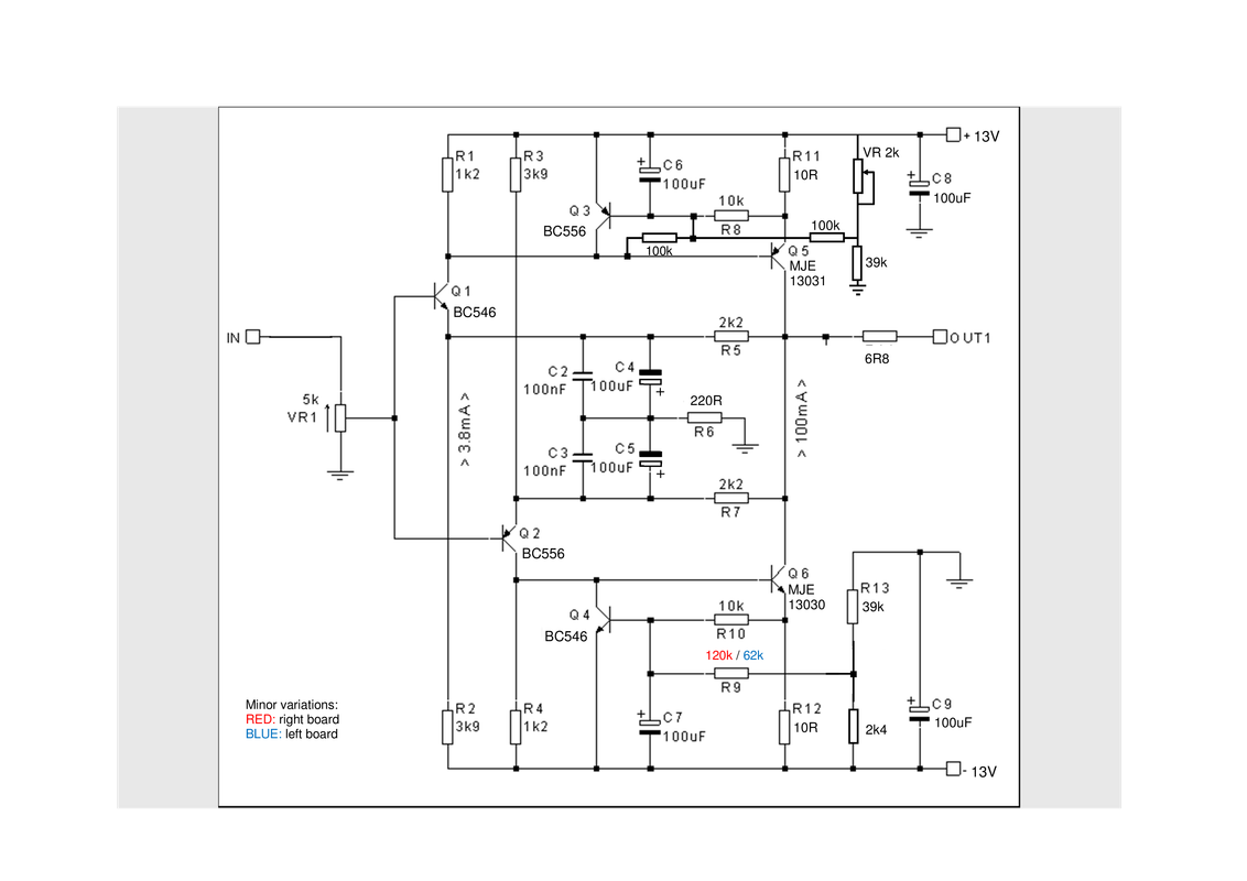
This one, Circuit 2:
https://sound-au.com/tcaas/jlhphones.htm
Built it over Christmas. You can JUST cram one circuit on a 9 rows x 25 holes piece of strip-board.
One comment re the circuit diagram: C4 and C5 are the wrong polarity and should be inverted.
I used BC546 / 556 for Q1/2; BC547 / 556 for Q4/3 and MJE15030/31 for Q6/5 as that is what I had to hand.
PSU: 12+12V 20VA transformer, 1N4004 bridge rectifier, 3x1000uF caps in parallel per rail with a 220R feeding a 12V zener and yellow LED in series to give 14V reference, zener and LED bypassed with 100uF cap which provides the base voltage to NPN / PNP cap multiplier. Output +/-13.3V was originally a little noisy (a slight 100Hz buzz), but has settled down after some use (will scope over w/end).
This is settling in nicely, driving DT990 'phones (slightly modified). The mid is nice and open, the bottom is full, tuneful and well defined, and the top is a bit peaky, but that's DT990's for you!
One question re DC offset: I was getting a large drift (200mV negative over about 3-4 hours) on first use, but now this is down to about 70mV (I guess this is the caps forming / settling in). I have it set to +50mV just after switch-on and this slowly drifts to -20mV after about 3 hrs use, mainly due to heat from the transformer, which I'm guessing is about 10W as the frame is warm but not hot to touch. Can this drift be improved upon? The reason I ask is I would also like to try a voltage divider across the output to see how it sounds working as a pre-amp, although a voltage divider (say 1k and 330R) with a final output cap of circa 3,3uF at the junction of the two resistors would suffice. Thoughts?
AP
 
A servo would be the complete cure.... other options, too late now I guess, would be matching of the input transistors and keeping them in thermal contact with other.

I seem to recall that this same circuit, with a few small changes, was actually used as the output stage of a JLH phono stage so yes it could make a decent pre. Ideally another one could be built but optimised as a pre amp and gain reduced by feedback but with due regard to stability as loop gain would be increased.
 
Cheers Arkless,
I did measure the input transistor Vbe's, NPN's were 0.696V and PNP's were 0.680V. I have a little rig which allows the voltage rails to be flipped so I can measure small transistors of both types with the same resistors. NPN emitter goes to -ve rail, 680k resistor feeds the base and 1k resistor feeds the collector, both from +ve rail and these rails are flipped for PNP's. Uses a LM7812 which gives 16µA base current so I can measure both Vbe and HFE.
I though about thermally coupling them but that would have left longer component legs. However I could try this with some insulation. Will this improve matters? I would like to improve thermal drift if nothing else than for winter / summer temperature variations.
At the moment it is installed in a cobbled-up wooden box (waiting for a nice metal one) which doesn't help matters as the heat builds up over time. Had this on all day on Saturday and by the evening it was sounding very "soft" i.e. lacking detail but after cooling down overnight all was well the following morning.
 
Spent about an hour last night making measurements of all the transistor Vbe's as the amp warmed up. The small signal transistors showed a drop in Vbe of typically about 20mV dc whilst the 100k 'balance' resistor (R9) showed a similar increase in voltage from 0.44V to 0.46V dc as the voltage at the connection of R9 & VR2 stays constant at 1.10V (only 2-3mV drift). This changes the balance current in R9 as it warms up which is what appears to be causing the dc drift on the output. I am going to try inserting a small signal diode between the trimmer and the supply rail so that as the transistor Vbe drops with increasing temperature, the connection point between the 100k (R9) and the trimmer (VR2) should drift down by a similar amount.
 
The diode trick works nicely. After some initial adjustment, at switch-on I now have about +50mV offset which drops over about 15 mins to <10mV. Over next hour or so there is then a very slow drift to about 0mV and on to about -10mV if you have it on for a few hours. This is with 250 ohm headphones. Lower impedance phones reduce these numbers a bit. Can you still get dual transistors that aren't SMD? I wonder if replacing the diode with the emitter-base junction of the second pnp of a dual transistor would improve this?
 
Fettling the psu at moment which is a bit noisy: too much ripple (100Hz) which is just audible. Apart from that, the instrumentation guy at work says it is a very nice amp with low distortion and flat frequency response out to nearly 200kHz before any visible roll-off begins. He said "it is spoilt by the psu, go away and fix it". :eek:;)
 
Was still getting about 100mV drift on the left channel and about 70mV drift on the right channel (measured from turn-on with no load on the outputs so worst case) so been playing with the 'dc' portion of the circuit based around Q3 and Q4. Seems very robust as even an electronics numpty like me can play around with it without too much bother! Anyway, after some experimentation I have got the drift down to 40mV negative over the first 10 or so minutes leading to a very gradual 'bottoming out' and then a very slow drift positive of about 10mV over 2 hours. This is with no load connected to the outputs. High impedance phones lower these figures and low impedance phones lower them still further. Bit 'spidery' at the moment (all soldered over the top surface) but I intend to tidy this up over the w/end after making sure there is no oscillation or other problems. Then I will get the instrumentation guy to make sure this hasn't drastically affected the distortion figures and take some photos.
 
Can't get measurements done for a bit now, some problem with a virus or something means we need to perform "social distancing" :eek:;)
Anyway, loaded the outputs with 33R resistors and drove these at 3.2V p-p (10mW so louder that I would ever drive headphones) 20Hz-20kHz flat as a pancake. 100kHz just slightly down and 1dB down at 200kHz. No signs of oscillations.
Couldn't get on with DT990 phones because of the v-shaped sound profile and perceived 'lumpiness' at the top-end so recently got some S/H Senn HD600. These are much better but had noticed a slight suck-out in the upper-mids. Some say the veil doesn't exist, but now I have got used to these, it certainly exists for me - human voices just don't sound right, 'high' S sibilants are there but 'low' S sibilants, FF and TH are recessed. Anyway I had some small 22mH chokes (about 40R resistance) so used a pair of these to make a "boost" filter by placing them in series with a small capacitor to make a series resonator (which has min impedance at resonance) with some damping across the resonator to limit the "peak" to about 3dB.
I wasn't sure where to start so initially used 0.33uF (1.9kHz) which was clearly too low, then 0.22uF (2.25kHz) which was better but still too low. Then used 100//68nF which measured to 0.18uF giving the peak frequency as 2.6kHz. 220R across this gives about 3dB "boost" and after a couple of listening sessions, this sounds much more natural to MY ears. [Actually it gives about 1dB insertion loss at the resonant frequency because of the resistance of the inductor which then rolls of either side to about -4dB at the extremes with dB being the measured voltages, not SPL]
 
Last edited:
Circuit modifications for interest:
JLH-Headphone-Amp-final.png

Only to DC domain. With HD600 on output left channel (which is still greater drift than right channel) has about +20mV at switch on, drifts to about -10mV after about 10-15 mins and then slowly drifts to about +5mV over about 3 hrs. Well pleased.
 
Its worth experimenting with a higher output resistor than 6R8. Some headphones were voiced for higher source resistance.
Try 47 Ohms or even 100 Ohms
 
Hi davidsrsb,
Yes I see what you mean but the original circuit actually had 4r7 output resistance so I used the closest value I had to hand.
AP
 
Headphones were actually originally meant to be driven from highish resistances, amplifiers often just had a big series resistor to the headphone socket.
The 1996 IEC 61938 standard recommended an output impedance of 120 Ohms

It was phones and portable players that made designers go for maximum possible swing from a limited power rail, that caused low resistance drive.
 
davidsrsb,
Thanks for the extra background info. Funnily enough I was talking to the instrumentation guy at work about this a few weeks ago and he said (iirc) that the extra output resistance gave better noise performance figures amongst other things (can't remember the entire conversation now)
 
This looks great.

What headphones have you settled with?

I have settled on some very easy to drive headphones (Shure 1540) and most commercial units are pushing out lots of gain that I don’t need.

How much power does this give? Is it tweakable?
 
Hi eastone,
Yes very pleased with it. Been listening to it with vinyl via a mm phono stage I've just built, on the end of a refurbished AR XA.
I'm using Sennheiser HD600 with some passive filtering to boost about 3dB at about 3kHz because despite what some say I hear the "veil" and this makes it sound right to me.
WRT output, I use it at just under half volume with CD and just over half volume with vinyl and there is bags of headroom. It will easily drive a nice looking waveform up to clipping into 33R. I have no sophisticated measuring equipment personally but the instrumentation guy at work put it on a FFT analyser and said the distortion was really low.
Gain is about x6.5 and each board dissipates about 2W split between the two o/p devices so sinking into the casework is more than adequate. Was a squeeze to get the amp boards onto 9 row by 25 hole veroboard especially as I had to tweak the DC drift a bit. Oh by the way I am no expert, just a humpty who likes to experiment. Definitely worth building. Think it cost me about 70-80 quid all in.
 
Sounds like rather too much gain for my Shures, they're 99dB and 46ohms - max input 1W. Do you know if it's possible to tweak the power output on this circuit downwards?

Very interesting that the circuit has some resemblance to Hiraga.

I am far less knowledgeable with DIY so I am very impressed with your build, even if you consider yourself a humpty!
 
Power is not an issue and it should work fine into the Shures. Gain can easily be changed and it could even be modded to give less output swing but more power in class A for lower impedance phones.
 
HD600 phones are 102dB SPL per volt so are slightly more sensitive than your 'phones. You also don't need to drive them to 1W. You will make yourself deaf. (1 volt rms into 46 ohm is 22mW giving you 98dB. Typically no more than 100mW required for transients and that would be LOUD.) The original circuit had slightly lower value resistors at R11 and R12 (6R8) but I didn't need this level of standing current for 300 ohm 'phones. 6R8 will give you about 100mA standing current but as Jez said you could even reduce these values a little further. Thing is you'd probably also need to change other resistor values but modern transistors typically have more gain than allowed for in the original design discussed in the link much further up thread so I reckon you could get away with 4R7 for R11 and R12 without worry. Trouble is you are then at about 2W per device so might need better heat dissipation. In fact with 100mA standing current (R11 and R12 at 6R8) you could probably drive your 'phones to just over 100dB without leaving class A as the peak current into your 'phones will still only be about 33mA.


advertisement


Back
Top