advertisement


Integrated Amp PSU Questions

nojobtoosimple

Active Member
Hi all,
I'm just planning my next project which will be an integrated amp.

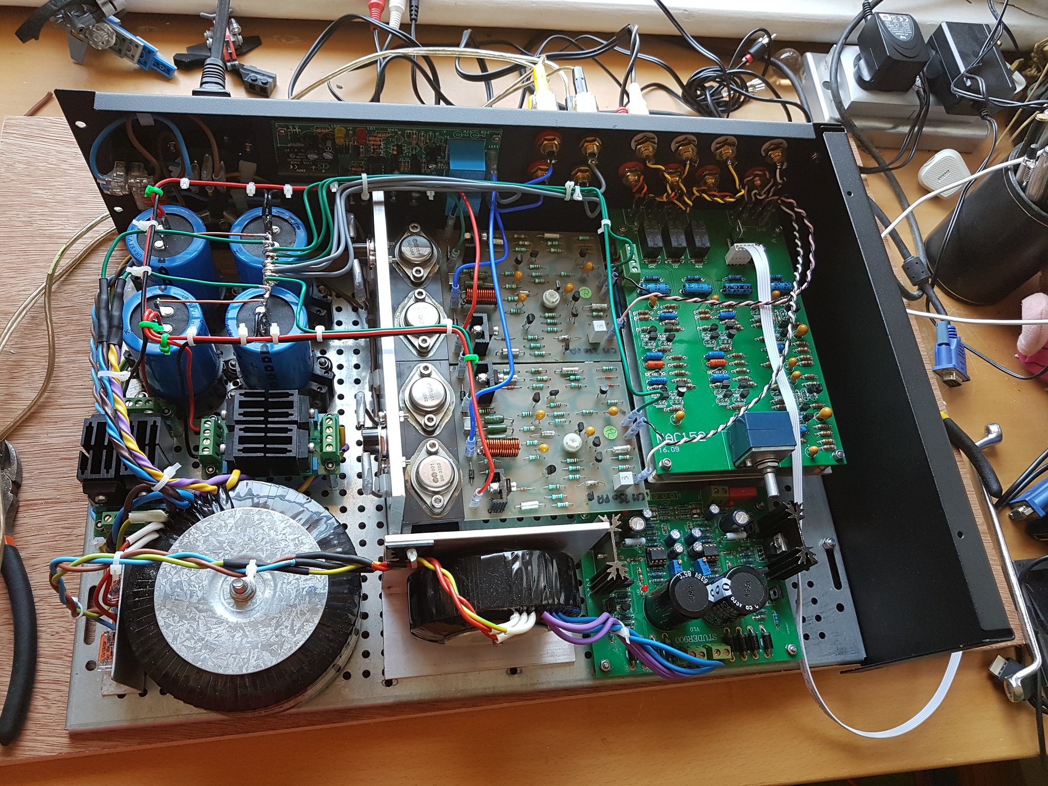
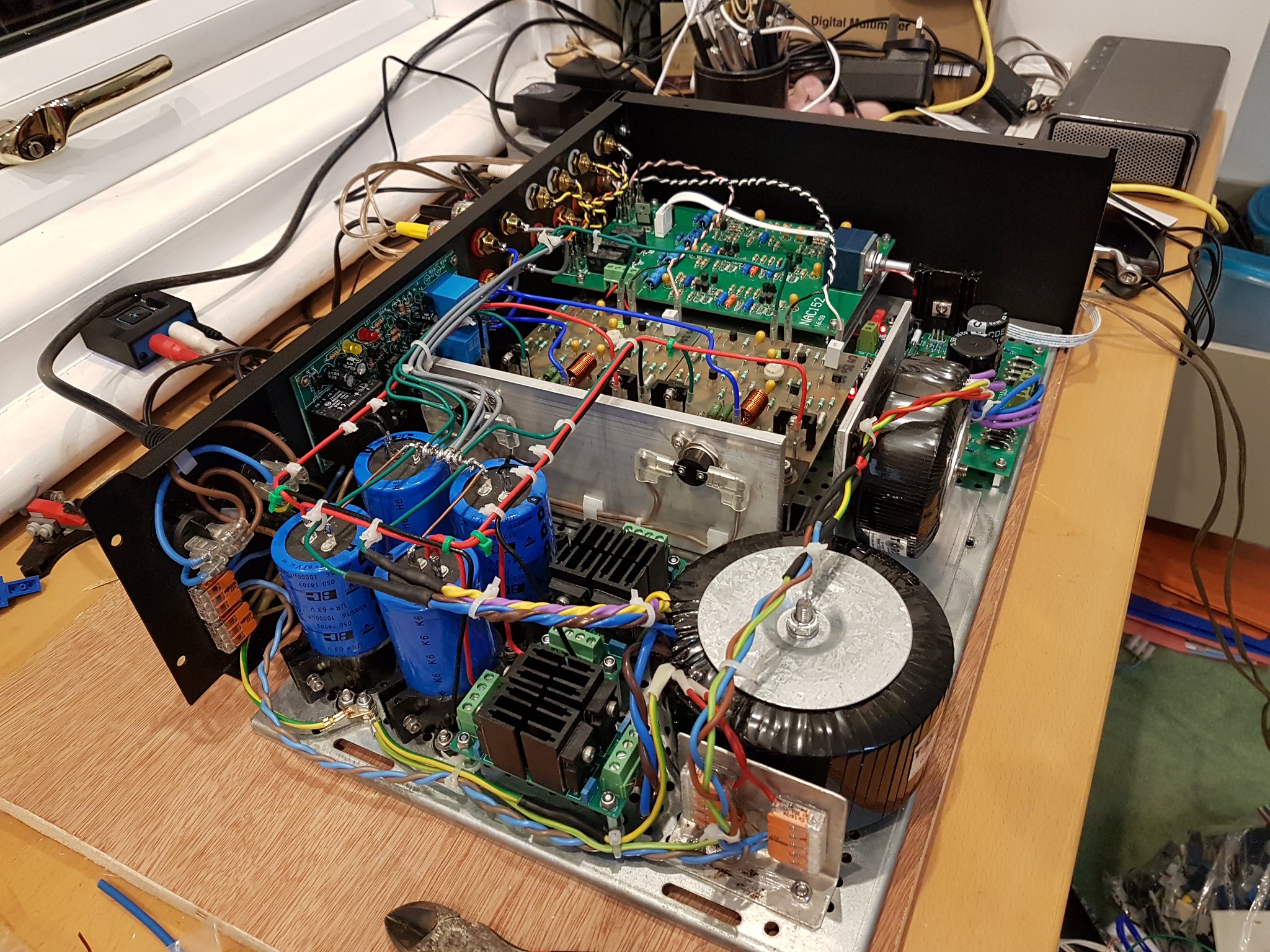
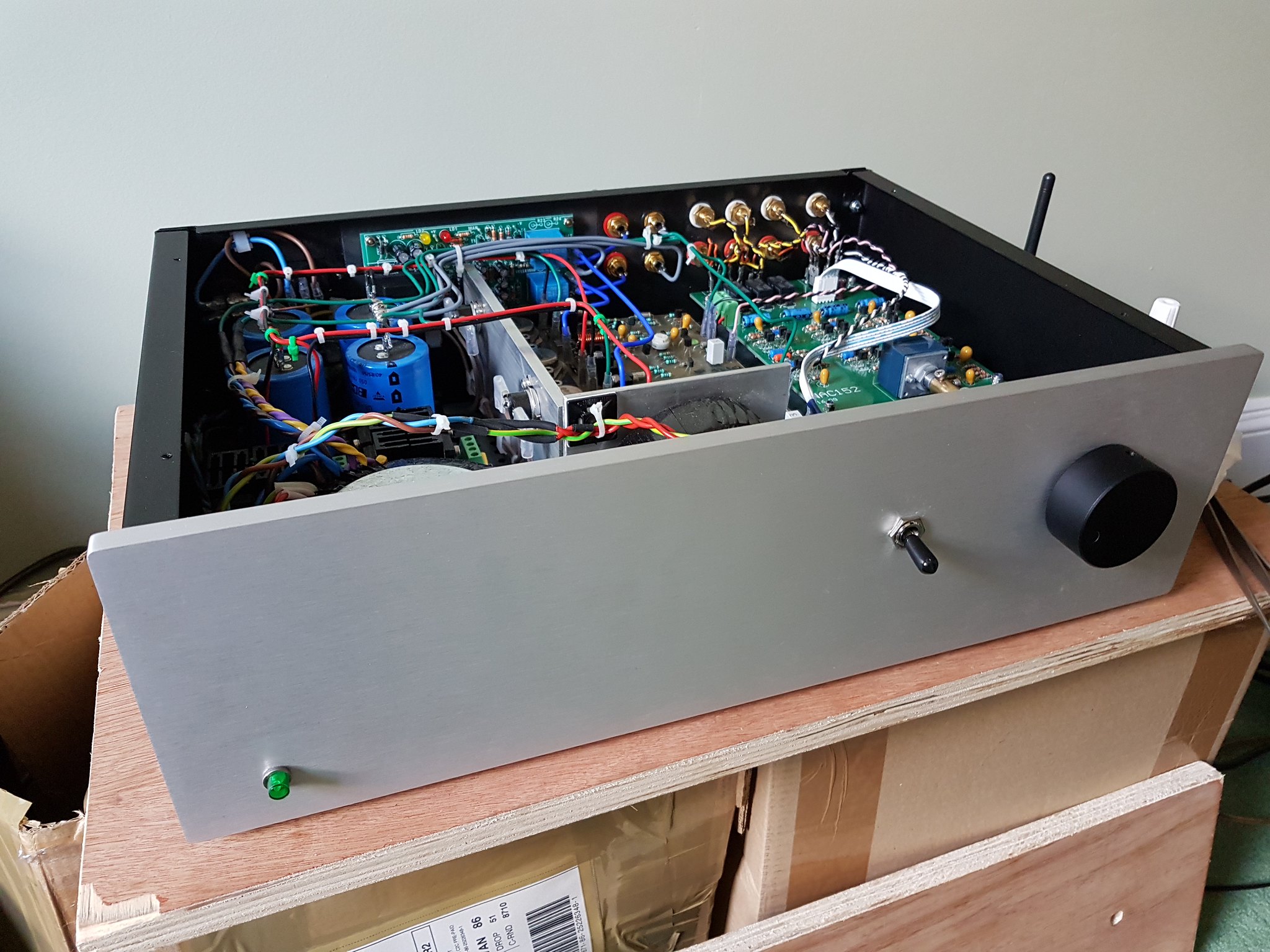
Power amp section will comprise traffo (250VA w 2x28V Secs), minicap (6x6800uF, 4x10uH), 2xNAPA (slightly modded), Velleman speaker board.

Preamp section will comprise traffo (72VA w 2x15V & 1x12V Secs), minicap with (6x2200uF, maybe with some L and/or some R), 2x+15V Reg & 2x-15V Reg powering 2xClass A preamp boards, 1x12V Reg powering an audio source selector and a Bluetooth module.

The first question, as you may have already guessed, relates to the Preamp minicap. Much reading of pfm threads has suggested to me that a CLCRC arrangement is often favoured. I am thinking that a pair of 10uH inductors followed by a pair of 0.22 or 0.47 Ohm resistors might be appropriate but the logic behind those thoughts is shaky, to say the least, and includes the fact that I have those components in stock.

The second question is about the ground arrangement for the 2 minicap boards. Can the preamp minicap ground float or should/must it be connected to the power amp minicap's ground or, alternatively, should they both be connected to a separate star ground, perhaps on the chassis ?

I'd be grateful for any thoughts and advice on the above.

Cheers,
Jon
 
This sounds like an interesting project. It's one step up from projects I've built myself, so I can't offer to much practical info, but I'll be watching it closely.
 
Jon,

Reading back through DIY posts going back to the year dot fitting inductors/ resistors to the PSU boards seemed to be "de rigueur" but most recently I have been steered away from it.

I don't claim to be an expert but people have advised me things sound "better" without......... I haven't actually carried out a direct comparison myself and my CAP6's do still have inductors fitted.

Regards

Richard
 
This sounds like an interesting project. It's one step up from projects I've built myself, so I can't offer to much practical info, but I'll be watching it closely.
Thanks Mike. This'll be my second integrated amp; I built the first one two or three years ago for my son (strictly speaking it's my third... I built one from Maplin kits about 40 years ago but it sounded terrible and I don't really count it). The last one was a monster, this one'll be a bit more modest in size but hopefully not in performance. I've attached some photos for your interest/amusement. :)

Jon
52238862122_15c52a0208_k.jpg

52239849093_4af151217c_k.jpg

52239849048_1b026da7db_k.jpg
 
Jon,

Reading back through DIY posts going back to the year dot fitting inductors/ resistors to the PSU boards seemed to be "de rigueur" but most recently I have been steered away from it.

I don't claim to be an expert but people have advised me things sound "better" without......... I haven't actually carried out a direct comparison myself and my CAP6's do still have inductors fitted.

Regards

Richard
Hi Richard, thanks for responding. Yes, what with hifi fashion and the general variation in opinion when it comes to what sounds better, it can seem that any four hifi buffs can come up with at least five opinions :) Nonetheless, I feel sure that there will be more technically oriented views on what constitutes the best approach and I'd likely be more guided by those, at least in the first instance (before the tweaking begins).

Regards,
Jon
 
Jon,

If i were to make one observation it would be about the VA capacity of the your chosen transformer and whether a larger one might be of benefit.

Regards

Richard
 
Regarding grounds, I think you'll have 3-4:
  • The mains earth, connected to your chassis
  • The CT of the pre-amp supply. I'm not familiar with pre-amps, so this may end up being shared with the signal output ground passed to the power-amp.
  • The signal ground of the power amp inputs, which as I indicated above may be shared with your pre-amp CT. (That's why I said "3-4".)
  • The CT of the power-amp supply, which of course also goes to the speaker negative.
As for transformers, I think 250VA will be plenty. We tend to get a bit silly with the size of transformers, and for an integrated using NAPA boards, I think you'll be fine. Class AB amps tend to be 50% efficient, so a 250VA transformer should should result in a maximum of approximately 120W, or 60W/ch, which is actually a fair bit of power.

Remember that most of the time the amp is outputting less than a few watts. It's only the brief transients that really need power, and they'll be fed by the smoothing caps (which are then refilled by the transformer).

As for CLCLC on the power-amp, the input stage of the power amp likes smooth voltage (making the inductors useful), but the output stage likes raw current (which is why some like to remove them). Since you have a single supply powering both input and output, I would be inclined to leave it as CLCLC.

Regarding the CLCRC on the pre-amp, it will draw very little current, so I would expect you to want as smooth a voltage as possible. Therefore, that should be fine.

Again, I'm not an expert in any of this, but this is my best estimation, based upon my experience.
 
Last edited:
Hi guys,

Thanks for responding and for the information/opinions. A couple of phono boards arrived this morning so I'll probably spend a few days building a phono stage before making final decisions on the way forward for the integrated. Watch this space though.

Regards,
Jon
 
Your preamp psu can just use larger resistors between caps, but if you are setting it up with +/-15V, and using lm317/337 for example, you want min 3V headroom so +/-18V inputs. The rest can be dropped by resistance between the caps. Say your raw supply gives +/-22V, you need sufficient headroom to allow for when the mains 'sags' so you may need to reduce your 22V to a notional 20V to allow for this. That gives you 20-18=2V. If your pre draws 40mA and each reg draws say 10mA that's a total of 50mA per supply leg. 2V/50mA=40ohm which you split as say 2 off 18ohm resistors to give say 1000uF>18R>1000>18>1000.
 
Your preamp psu can just use larger resistors between caps, but if you are setting it up with +/-15V, and using lm317/337 for example, you want min 3V headroom so +/-18V inputs. The rest can be dropped by resistance between the caps. Say your raw supply gives +/-22V, you need sufficient headroom to allow for when the mains 'sags' so you may need to reduce your 22V to a notional 20V to allow for this. That gives you 20-18=2V. If your pre draws 40mA and each reg draws say 10mA that's a total of 50mA per supply leg. 2V/50mA=40ohm which you split as say 2 off 18ohm resistors to give say 1000uF>18R>1000>18>1000.
Hi,

Thank you very much for your suggestion. With 2V @ 50mA a 1W resistor should be plenty too.

Regards,
Jon
 
You will need to work out what resistors you need from the head room less the leeway and your measured current draw under your circumstances, but the principle is what matters of course. Yes, 1W will be sufficient to withstand the high initial charging current as it will be just a short initial burst.


advertisement


Back
Top