teddy_pardo
Trade: Teddy Pardo
I was asked by many to summarize the long replacing the ALWSR pre-regulator thread, and provide a short howto for people who just want to make it without reading the whole thread.
A quick background
The ALWSR has a pre-regulator, which is based on a monolithic linear regulator. Through experiments, I discovered that the performance of the ALWSR can be significantly improved by providing it a smoother input containing less high frequency noise. It was first done using an LC filter, and then using a VBE (Gyrator) circuit. Since both the super regulator and the pre regulator are linear regulators, the whole circuit is limited in its abilities to deal with high frequencies as exists on the mains, and generated by the rectification process. A VBE circuit consists of a low pass filter, feeding the base of a transistor configured as emitter follower. The role of the transistor is to provide current with lower impedance. This howto explains how to replace the pre regulator by a VBE.
The VBE
It turns out that the filter and the transistor have significant effect on the performance. The best circuit so far consists of a second order filter (RCRC), and a FET transistor or a Darlington made of discrete components (more on that later).
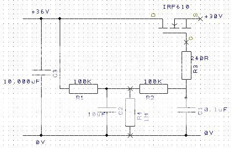
The circuit is described here (many thanks to Hacker for the drawing)
The Filter
Best results were achieved using film capacitors. Electrolytic capacitors should be avoided here. For C2 Im using 6-10uF polyester (MMK, MKS etc), and for C1, the second filter, Im usually using a 220nF polypropylene. Class X2 capacitors (AKA suppression or AC capacitors) are doing a great job here.
R1 and R4 effect the dropout, Im usually using 64K/1.5M for low dropout, or 100K/1M when I can afford a higher dropout.
The transistor
Two main options exist, FET or Darlington. FET has a larger dropout and higher output impedance, most people on the forum preferred FET as it is giving a better bass. Personally I found that I like both, and it depends on the application. I also discovered that high impedance at the output of the VBE adds bass, and that may be the cause of the difference in sound. This bass is IMO slightly artificial but nonetheless pleasant to the ear. You can make a simple experiment by using just the VBE circuit without the super-regulator (the SR reduces the output impedance of the VBE). Youll get a sound which is rich in bass, and very pleasant, something like a tube amplifier.
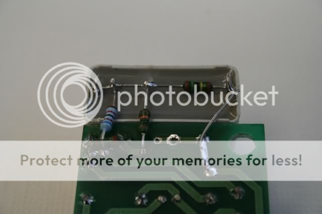
With a FET, R3 is mandatory to avoid oscillations. I found that even with a Darlington it provides a slight improvement. Note that in order to use this resistor youll have to make a cut on the PCB (see picture below). Smaller values can be used too, I've used 118R successfully.
In order to make a Darlington I use bc547c and D44H11, together they provide a HFE of about 100,000, allowing relatively low output impedance (few ohms). If your system has sufficient bass I'd personally recommend Darlington (but most other people prefere FET, so make your choice...). Here is how I build a Darlington transistor from discrete components:

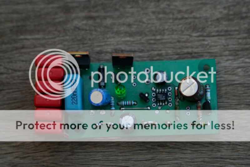
Here are some pictures of the modified ALWSR board:
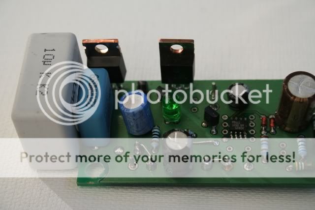

This one is made of seven 1uF MKS capacitors:
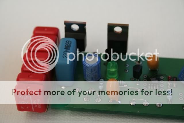
Note the cut on the PCB below the blue 64K resistor. This cut is made to allow using R3 to avoid oscillations.

A quick background
The ALWSR has a pre-regulator, which is based on a monolithic linear regulator. Through experiments, I discovered that the performance of the ALWSR can be significantly improved by providing it a smoother input containing less high frequency noise. It was first done using an LC filter, and then using a VBE (Gyrator) circuit. Since both the super regulator and the pre regulator are linear regulators, the whole circuit is limited in its abilities to deal with high frequencies as exists on the mains, and generated by the rectification process. A VBE circuit consists of a low pass filter, feeding the base of a transistor configured as emitter follower. The role of the transistor is to provide current with lower impedance. This howto explains how to replace the pre regulator by a VBE.
The VBE
It turns out that the filter and the transistor have significant effect on the performance. The best circuit so far consists of a second order filter (RCRC), and a FET transistor or a Darlington made of discrete components (more on that later).
The circuit is described here (many thanks to Hacker for the drawing)
The Filter
Best results were achieved using film capacitors. Electrolytic capacitors should be avoided here. For C2 Im using 6-10uF polyester (MMK, MKS etc), and for C1, the second filter, Im usually using a 220nF polypropylene. Class X2 capacitors (AKA suppression or AC capacitors) are doing a great job here.
R1 and R4 effect the dropout, Im usually using 64K/1.5M for low dropout, or 100K/1M when I can afford a higher dropout.
The transistor
Two main options exist, FET or Darlington. FET has a larger dropout and higher output impedance, most people on the forum preferred FET as it is giving a better bass. Personally I found that I like both, and it depends on the application. I also discovered that high impedance at the output of the VBE adds bass, and that may be the cause of the difference in sound. This bass is IMO slightly artificial but nonetheless pleasant to the ear. You can make a simple experiment by using just the VBE circuit without the super-regulator (the SR reduces the output impedance of the VBE). Youll get a sound which is rich in bass, and very pleasant, something like a tube amplifier.
With a FET, R3 is mandatory to avoid oscillations. I found that even with a Darlington it provides a slight improvement. Note that in order to use this resistor youll have to make a cut on the PCB (see picture below). Smaller values can be used too, I've used 118R successfully.
In order to make a Darlington I use bc547c and D44H11, together they provide a HFE of about 100,000, allowing relatively low output impedance (few ohms). If your system has sufficient bass I'd personally recommend Darlington (but most other people prefere FET, so make your choice...). Here is how I build a Darlington transistor from discrete components:
Here are some pictures of the modified ALWSR board:
This one is made of seven 1uF MKS capacitors:
Note the cut on the PCB below the blue 64K resistor. This cut is made to allow using R3 to avoid oscillations.
")