
Are the schematics on here of any use? http://www.acoustica.org.uk/t/naim/power_amps.html
You are using an out of date browser. It may not display this or other websites correctly.
You should upgrade or use an alternative browser.
You should upgrade or use an alternative browser.
Free but stuffed! Naim Nac32/160/SNAPS
- Thread starter SPH
- Start date
Are the schematics on here of any use? http://www.acoustica.org.uk/t/naim/power_amps.html
It didn't when I first looked at it but it's starting to make more sense the more I read. I still have a bit of a hard time relating it to the actual physical layout on the board.
Ok. I actually put some time into reading the diagram and it now makes sense. It was actually a great help in figuring out what everything is.
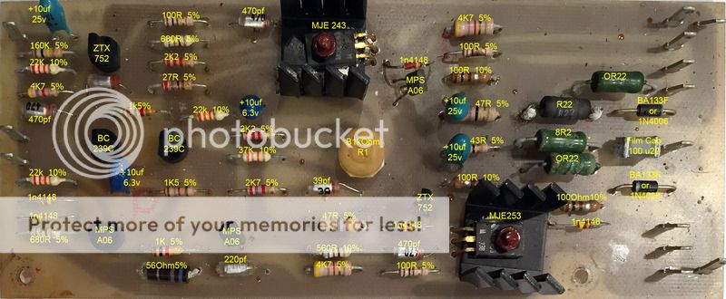
Here's my revised listing.
A few silly mistakes on my part but I'm getting there.
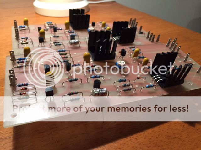
I'm still unsure about that film cap at the far right, middle. In the schematic it's listed as a 220... something. The one on the board is labeled u22 100 which I think is 0.22uf, 100v breakdown. What should it be?
Next issue; I keep reading that there are some errors in the schematic. What are they? I still have discrepancies between the diagram, the left channel and the right channel and without a rock solid, known good reference I'm not sure what to believe. There are a few great images on the net but they're not high enough resolution to pick resistor values or read transistor labels.
Here's my revised listing.
A few silly mistakes on my part but I'm getting there.
I'm still unsure about that film cap at the far right, middle. In the schematic it's listed as a 220... something. The one on the board is labeled u22 100 which I think is 0.22uf, 100v breakdown. What should it be?
Next issue; I keep reading that there are some errors in the schematic. What are they? I still have discrepancies between the diagram, the left channel and the right channel and without a rock solid, known good reference I'm not sure what to believe. There are a few great images on the net but they're not high enough resolution to pick resistor values or read transistor labels.
Its the bridge rectifier for the +24V supply to the pre-amp.
Pete
Brilliant, thank you!
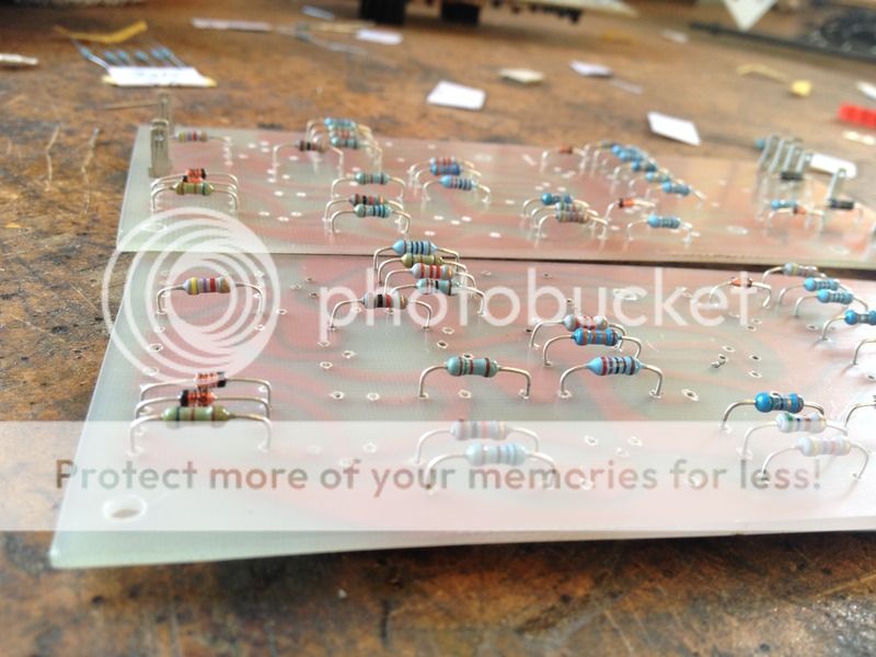
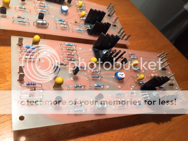
Underway. Resistors and diodes were almost all stocked items so they're all installed.
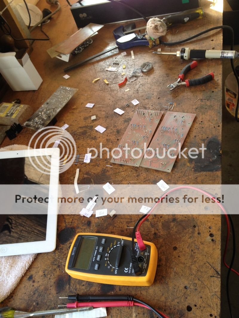
I reused the dagger connectors off the original boards. The local shop wanted something like $20 for a bag of 100. Farnell has them for about $4 but I figured the old boards are never going to get used again so I can happily reuse them.

Compared to the original boards the drilling is a bit rough. The back side is fine and all the soldering went really nicely. The drill has just fractured the resin a little on the face. It's not going to make any difference to the end result but, eh, makes for conversation.
I realised once I'd finished installing all the resistors and diodes that I'd installed left in the overload protection components. I guess I'll get the amp working in something like its original configuration and then get to modding.
I reused the dagger connectors off the original boards. The local shop wanted something like $20 for a bag of 100. Farnell has them for about $4 but I figured the old boards are never going to get used again so I can happily reuse them.
Compared to the original boards the drilling is a bit rough. The back side is fine and all the soldering went really nicely. The drill has just fractured the resin a little on the face. It's not going to make any difference to the end result but, eh, makes for conversation.
I realised once I'd finished installing all the resistors and diodes that I'd installed left in the overload protection components. I guess I'll get the amp working in something like its original configuration and then get to modding.

John_73
pfm Member
If you wish to keep to the original performance specs. and sound those resistors have to be 0.22R, and ideally wire-wounds of the same wattage as the originals.
You're doing an amazing job with those boards. Where they hard to cut to size? I'm still toying with the idea of etching a couple of my own for experimenting with. Do you still have the scans that include the drill holes? You mentioned the drill fracturing the pcb a little. Whilst your work looks fine to me if you want to avoid that in the future, you can place tape over the entire pcb first, and that largely avoids any minor fracturing. A drill press helps too.
Hopefully you should be up and running with it soon now. Look forward to seeing the updates")
John.
You're doing an amazing job with those boards. Where they hard to cut to size? I'm still toying with the idea of etching a couple of my own for experimenting with. Do you still have the scans that include the drill holes? You mentioned the drill fracturing the pcb a little. Whilst your work looks fine to me if you want to avoid that in the future, you can place tape over the entire pcb first, and that largely avoids any minor fracturing. A drill press helps too.
Hopefully you should be up and running with it soon now. Look forward to seeing the updates
John.
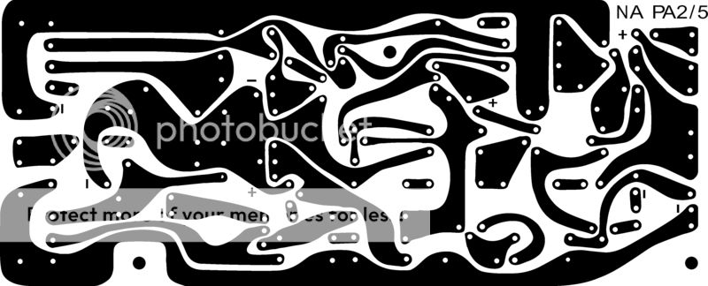
For the most part the holes are all spot on. If you do end up making a pair just don't drill the heat sink holes. Leave them untill the transistors are installed and drill them to fit. I think mine will need to be made a bit oval for everything to line up.
I cut my boards out on my bandsaw and then squared them up on a bench sander. The PCB absolutely ruined my bandsaw blade. I mean rounded over teeth by the time I'd cut the 6 or so I made. It was a brand new blade too!
The tape is a good idea, should have thought of that. I drilled them using my knee mill. Don't have a drill press as such anymore.
I found all the parts I need on Element14 last night. I should have just ordered all the gear myself. I find that's usually the case. It's rare that a store employee is as committed to your project as you are. Anyway, they've got Vishay R22, 3W wire wound resistors and the 8R2 3W. They also have all the transistors I'll need, the correct tants etc.
I'll see what the local comes back with this week and then order parts myself if they have trouble.
John_73
pfm Member
Thanks for posting that. If I ever get around to trying out one of those self etching kits (been meaning to for years!) then this'll be my first project. Looks like you got perfect results first time around. They're probably better than the originals
I've read with cutting pcbs it's often easier to score them heavily with a Stanley Knife or something similar. Score on both sides of the board. Then snap it off quickly, over the corner of a desk or something, and file off any rough edges. I don't have a band saw so that's what I'd have to do.
By the way, have you got measurements taken from the original boards, in mm? If I get around to doing this I'll probably cut the pcb to shape first, then etch, to save fluid and materials.
Are you going to be stripping down & respraying the chassis?
PigletsDad
My intelligence test came back negative.
They need to be reasonably high power; this means wire wound (or exotic high power films).
And yes 22Ohms will not work - needs to be 0.22Ohm
And yes 22Ohms will not work - needs to be 0.22Ohm
Hi guys, I'm still working on the NAP, just having a hard time getting parts. I've given the local supplier the sack. Too expensive and WAAAAY too slow. I ordered parts over a month ago and still haven't seen some of them.
I'm putting together an element14 order but I'm unsure what to use for the (I think) styrene capacitors. I need 3x470pf and 2x39pf for each board. I have the 220pf even though they're about 4x the physical size of the originals and cost $10 each! Can anyone suggest appropriate components? Even just the right style of capacitor would be fine, I can't seem to find anything that looks similar. I don't know if they don't make that style anymore or if I'm just not looking in the right place.
*edit*
Duh, found them. Anyway. Those suckers are EXPENSIVE... in the scheme of things. Just to be sure, this is what I'm after, yeah?
Element14 don't list a 39pf cap so I've gone for a 47pf. Will that do the job?
John_73
pfm Member
Have you tried here?
http://au.rs-online.com/web/c/passi...polystyrene-film-capacitors/?searchTerm=220pF
By the way just had a look at your annotated pcb photo, and I think two of the caps on your board should be 100uF, not all five being 10uF. Might be worth double-checking with any other Nap160 owners on here.
http://au.rs-online.com/web/c/passi...polystyrene-film-capacitors/?searchTerm=220pF
By the way just had a look at your annotated pcb photo, and I think two of the caps on your board should be 100uF, not all five being 10uF. Might be worth double-checking with any other Nap160 owners on here.
Have you tried here?
http://au.rs-online.com/web/c/passi...polystyrene-film-capacitors/?searchTerm=220pF
By the way just had a look at your annotated pcb photo, and I think two of the caps on your board should be 100uF, not all five being 10uF. Might be worth double-checking with any other Nap160 owners on here.
Thanks for that, you're right. The 6.3v tants are 47uf.
Rs-online only seem to have 220pf styrene caps. Pretty much the same price too. They must be uncommon these days.
John_73
pfm Member
Thanks for that, you're right. The 6.3v tants are 47uf.
Rs-online only seem to have 220pf styrene caps. Pretty much the same price too. They must be uncommon these days.
That's frustrating - we're pretty spoilt for choice over here with component suppliers. I could always order from RS here and send them onto you as a last resort, but obviously that's not ideal for you time-wise.
That's interesting about the caps being 47uF. I can't see any difference (other than the transistor mounting and slight pcb differences to accommodate that) between your Nap160 and my Nap120 pcbs (was comparing them earlier with your photos). If I ever get the upgrade urge all I'd need is a bigger chassis and appropriate transformer.
Anyway, PM me if you ever need those components.
Ok, so I'm getting there.
Went to the only other parts supplier in town and got the last few resistors I needed. They also had the tants I was after. The 47uf are 16v rather than the 6v ones that were on the original boards but I'm confident they'll be ok. 10uf are 35v as original.
Almost all of the transistors are installed, just waiting on the ZTX 753's.