advertisement


Free but stuffed! Naim Nac32/160/SNAPS

This seems to me to be a ridiculously complex job due to the OP's inability to actually diagnose the problems

No arguments from me.

The diodes in place look to be working but there are stories here and on other sites of them giving out on initial power up. I'm not in a rush to replace parts I don't have to. I'll get the caps installed, stick a light bulb in series with the mains and see what I get.
 
Actually just put the T4 fuse in, don't connect the amp boards and put about 3K across each res cap so that they can drain down when you power off.

If it fires up and you get about +/- 38V then it's cool.

Take the 3k resistors off when you're done.

If you have lopsided voltages or it just goes phut then there are diode issues.
 
Get a DVM ( will cost a small amount, a few dollars /pounds) if you don't have one.

Then you can measure things like diodes, and see if they are OK, check voltages and so on.

Otherwise you are blundering in the dark.
 
Get a DVM ( will cost a small amount, a few dollars /pounds) if you don't have one.

Then you can measure things like diodes, and see if they are OK, check voltages and so on.

Otherwise you are blundering in the dark.

Yes, I have a couple.
 
If you have a DVM, unwire the diode bridge, and measure the resistance each way (swapping + and - probes) between each of the input pins (marked ~) and the outputs (+ and - respectively). You should get open circuit in one direction, and conduction in the other. If any of the measurements conducts both ways, or doesn't conduct at all, the diode bridge is bad. Otherwise, wire it back into place.

You can also test transistors with DVM. Some have special test sockets - if not let me know, and I will describe a trick for a rough and ready test that works with a basic dvm.
 
Sorry, I was being a bit vague again. I said 'look to be working', what I meant was 'have been tested and are working'. The reason I was chasing replacements is that it's s lot easier to have the parts and not need them than find I need them and have to wait/pay postage on yet another parts order. I placed the order last night and included two of the block style bridge rectifiers just in case.
 
Ok guys, I've finally knuckled down and got the caps installed. I crossed my fingers and fired it up. Nothing caught fire! Nothing even went pop. So far so good. I'll throw out some numbers and hopefully you guys can let me know what's what. Everything is not as it should be, I think.

Across the individual res caps: 42.7v.
Across the 3300uf cap 38.8v
Across both caps :85.6v
At the 24v regulator: 24.4
Yellow wire tap to ground: 31v AC
I get that same 31vac reading at a few point on the diode bridge.

So here I am, in the dark again. Hoping someone can hold my hand once more ;)

I actually had a go at shooting a video. You'll be able to see and hear me floundering in the dark instead of just reading about it!
 
I think those figures are ok. The NAP boards work on about + and - 40v. So an approx 30v ac output from the transformer once rectified will give you 30 X 1.414 dc output so about 42.4v (+ and -) to the boards. These figures are at no load. Across both caps you'll get twice 42.4 or 84.8v so that's on track. The figures are a teeny bit high but as I said its at no load and your mains voltage might be a bit high as well.
what voltage rating are your reservoir caps?
 
Yeah, ok. That sounds promising. Mains is reading 250v.

*edit* 250v!? I must be remembering that wrong. I'll go check after tea.

Checked, yep, 251vac. That is juuuuust within the acceptable limits.
 
Aaaand if you want a quick laugh here's me jabbing a multimeter into a powered up amp. Only one spark.

Oh, timH, the caps are 63v.
 
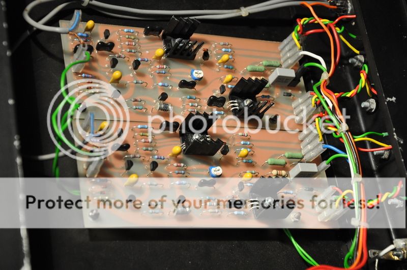
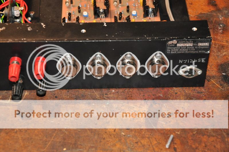
Final parts turned up. Well, all except for 2 wire wound 8R2 resistors. I already had some 1w film resistors in that position from the not-so-great local store order. I'll replace them as soon as they turn up. I got the output transistors replaced too, new isolation washers and heat shrink on the exposed leads. Luckily there was enough spare lead on the red/green/yellow leads to shorten them up a touch to get rid of the dodgy ends.

final1.jpg


final2.jpg


final3.jpg


As always, all opinions and feedback greatly appreciated. If anyone can see any glaring issues, of course, please bring them up.
 
Nice job! I'm just closing up my last (3rd) NAP 250 (although one channel might have a problem I'll post about.) I used all 12 original boards but I'm going to make some "spare" PCBs... presensitized boards just came today and I've never printed boards before (beyond pen drawn in shop class as a kid.)


advertisement


Back
Top