advertisement


DIY tonearm

I haven't tried Anchor yet. I thought that I would cock it up myself before i resort to seeing about getting them made. This is, after all , DIY. :D

There is also a budget to this project .. a low budget at that. I suspect that commissioning near one off magnets will cost in the hundreds of pounds. As my best guess of the end shape required is just that.. a guess , then this is an experiment. One off produced magnets will start to cost more that buying an original Schroeder arm.

I have to source an affordable cnc manufacturer for the aluminium parts ( top and bottom holding plates ) which will require me to get the cad programme written by someone because it is beyond my ken. One-offs are always very expensive and as no one has expressed an interest in doing this project the expense will all be mine.

I know a man who does wood though, and thats a start.;)
 
They have the wrong profile... there is a 138 page thread on DIyaudio if you would like to explore the subject in greater depth? :D

Short answer.. they have the wrong flux field. ....there is one magnet in the arm and one below it . To work they must attract each other to hold the arm stable. Two cones in the correct orientation for cones would be repelling each other.
 
I have to source an affordable cnc manufacturer for the aluminium parts ( top and bottom holding plates ) which will require me to get the cad programme written by someone because it is beyond my ken.
It's a one-off. Why does it need to be CNC? Why can't you use a conventional lathe, miller or lathe set up as a miller? CNC is about speed and repeatability. Neither of these are important to you.
 
Agree totally CNC v non - any decent turner/miller/tool-maker could work from a detailed but simple sketch(s), you just need to make sure that all dimensions, including finish(es) are spec'd.

I must be missing something - magnet in the arm and one below it, opposite poles attracting - the magnets would "lock" together. Same poles facing each other, N or S, and at some point, one would "float" above the other.
 
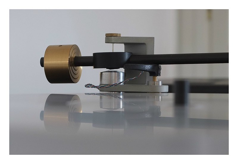
The magnets attract, but are kept apart by the suspension filament. The concept looks simple, but having read some of the contribution to the threads on DIYaudio by Frank Schroeder it seems more complicated, for example keeping the tracking weight consistent as the cartridge tracks warps. Schroeder Mk 2:

42001818124_a59992d869_c.jpg
 
If I understand correctly, the arm hangs by the thread and the two magnets basically steady the assembly by keeping the tread taught.
Looking at these pic's, the arm magnet looks to be a simple squat barrel shape, not shaped to the arm -

https://oswaldsmillaudio.com/schroder_reference

I would be inclined to experiment with the bottom magnet, not as a permanent magnet, but as an electromagnet - being DC it should not cause any interference problems. Possibly what is happening in the Mk2?
Using an electromagnet would also allow limitless variation at minimal cost, in pole piece shape, it being soft iron, which is the likely answer to the tracking weight problem, and more. A longer arm would also help.
 
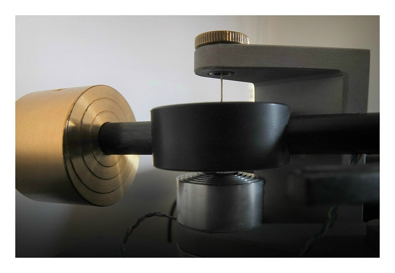
This is what Frank described the shape of the magnet in the arm to be...

" I wrote "barrel-segment" shaped, not barrel shaped. Imagine the upper magnets "face" to have two radii, the smaller at a right angle to the armwand, the longer one along the armwand. Again, smaller radius as seen from the front, large radius when looked at from the side."

It can be seen in the photo of it that I posted on the previous page.
 
The magnets attract, but are kept apart by the suspension filament. The concept looks simple, but having read some of the contribution to the threads on DIYaudio by Frank Schroeder it seems more complicated, for example keeping the tracking weight consistent as the cartridge tracks warps.

Record warps are not really a problem for this arm.. the deflexion at the magnets caused by a warp is tiny ( and if your records are SO warped that it does have an effect why are you playing them ? :confused: ) so that the deflexion in the magnetic field is negligible.

The complication in the design of the optimal shape for the magnets is to design it so that the VTF is constant across the record and any alteration in the VTA does not grossly affect the VTF. Hence, I believe , the complicated barrel stave shape is arrived at.

As far as I am aware Frank Schroeder uses these shaped magnets for his Reference arm ( which is very costly ) I think that ,maybe , his more affordable arms come with disc magnets with flat faces. ( I could be wrong though.. never seen a Schroeder in the flesh and probably never will ) Obviously Frank does not give away the more pertinent technical details of his arms but he has generously passed on quite enough information to point one in the right direction.

Personally, If I were he I would have by now commissioned bespoke shaped magnets and saved myself the hours and hours of work necessary to shape the magnets for each arm.
 
Joe

You're quite correct, changing VTF as the arm tracks across the record is a bigger issue. The Mk 2 shown above is my arm; VTF changes depending on how high the sensing pad is on the balance, so I assume it also changes over warps, although probably not enough to worry about. Interestingly, despite worries to the contrary I have only had to adjust the gap between the magnets twice in about 12 years
 
Joe

. The Mk 2 shown above is my arm; s

Ah.. nice. You are fortunate.

Out of interest...are the magnet faces on your arm flat?

Also..if you would.. I read on DiyAudio ( Frank himself ) that the lower magnet should be level with the platter. I cant really get my head around that as it would mean that the cartridge that you use could only be as the thickness of the magnet gap... and that doesn't make any sense.
I cant go through 138 pages to find the quote though.
 
Ooh, someone with one of these arms :) This would be a great thread to post some close up photos and some rough measurements :)

Stefan
 
Joe

The lower magnet, as you have concluded is way above the level of the platter. Looking at it I'm guessing that the lower magnet is flat, the upper seems profiled. In this photo the arm is at rest which raises it above horizontal; when playing the gap is more uniform and equates about to a business card thickness which is the recommendation. The arm only gets adjusted when it has a new cartridge fiited; there is some art in getting them to work optimally, and even the various screw tighnesses can make a difference. The big bonus is that cartridges seem to last longer on it

The deck manufacturer recommended a Naim Aro at the time which is what I expected to get but this was a cancelled order with the importer otherwise I don't think I would have waited; order periods had gone out to over a year. Frank is very helpful and seems a real enthusiast; I'm sure he can provide enough information to construct something similar. I can't supply dimensions, but there are other DIY examples on line which should help

42160829854_1cb9876e0f_c.jpg
 
. I can't supply dimensions, but there are other DIY examples on line which should help

John... thank you for posting... good information/confirmation.

I don't want or need dimensions .. that would be slightly against Franks wishes on't'other site.

And it wouldn't quite be DIY.
 
I am gathering information with a view to making my own tonearm.

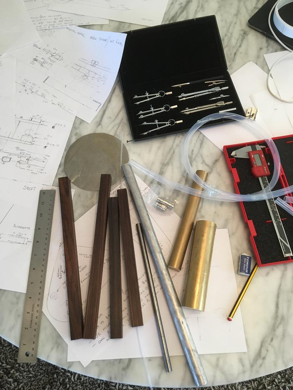
Design finalised, research done, all questions asked and now sourcing / gathering all the various materials needed and tracking down the various skilled trades I need the help of.

IMG_1268.jpg
 
Last edited:
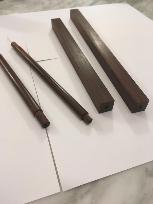
Most importantly for me I found a way of shaping the magnets by cold grinding. That for me was the critical start point . Just waiting for some silicon tubing to arrive to decouple the counterweight and then all the metal goes off to my man with a lathe.


Nice wood ;)


Mmmmmmm... wood.

IMG_1274.jpg


advertisement


Back
Top