
You are using an out of date browser. It may not display this or other websites correctly.
You should upgrade or use an alternative browser.
You should upgrade or use an alternative browser.
Deltec / DPA
- Thread starter Tony L
- Start date
NeilK
pfm Member
You are very lucky! The 10 - 24 is a beautiful DAC, very rare but based on dpa's own proprietary pulse array technology. If it's working then that's excellent, I'm not sure about servicing / maintenance of this, and of course the FPGA chips are, I think, unobtainable.
I used to have a T1, it's pretty much a Marrantz CD player in a dpa case, I didn't like it.
I used to have a T1, it's pretty much a Marrantz CD player in a dpa case, I didn't like it.
Selling a DSP50 line stage if anyone is interested.
You are very lucky! The 10 - 24 is a beautiful DAC, very rare but based on dpa's own proprietary pulse array technology. If it's working then that's excellent, I'm not sure about servicing / maintenance of this, and of course the FPGA chips are, I think, unobtainable.
I used to have a T1, it's pretty much a Marrantz CD player in a dpa case, I didn't like it.
It’s working and sounds wonderful.
eran shokroun
Member
Don't be shy, give few photos.... Indeed rare digital conversion Land mark it Is.It’s working and sounds wonderful.
So thats what they are ! Ive got a couple of those thick film circuit boards in my spares box but I didnt know where they came from until now.Thick film op-amps anyone?
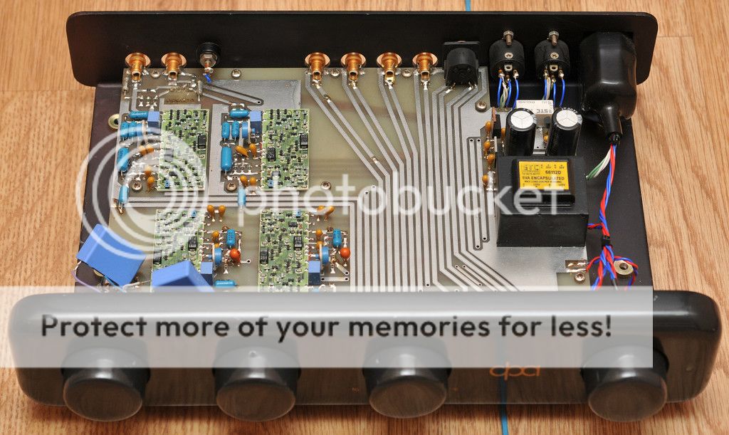
Still one of the best pre-amps around?
Thick film op-amps anyone?
Still one of the best pre-amps around?
That image reminds me, I found similar Wima 1uf film caps in my other pre. Do the originals blow if something upstream lets go? I think the originals are also film/poly types so it doesn't seem like an obvious upgrade...?

Sorry just seen this. I'll try to find them and see if they are still serviceableI'd be interested in them if they are going spare? One of the replaced tants on my boards in the phono stage of my early version is connected only 'loosely' to the board at best.
Found them and they look just like the ones shown with DH-OA32 written on them. I dont know if they still workThat image reminds me, I found similar Wima 1uf film caps in my other pre. Do the originals blow if something upstream lets go? I think the originals are also film/poly types so it doesn't seem like an obvious upgrade...?
but I'm happy to send them to you as I have no use for them. Wont be until after xmas though.
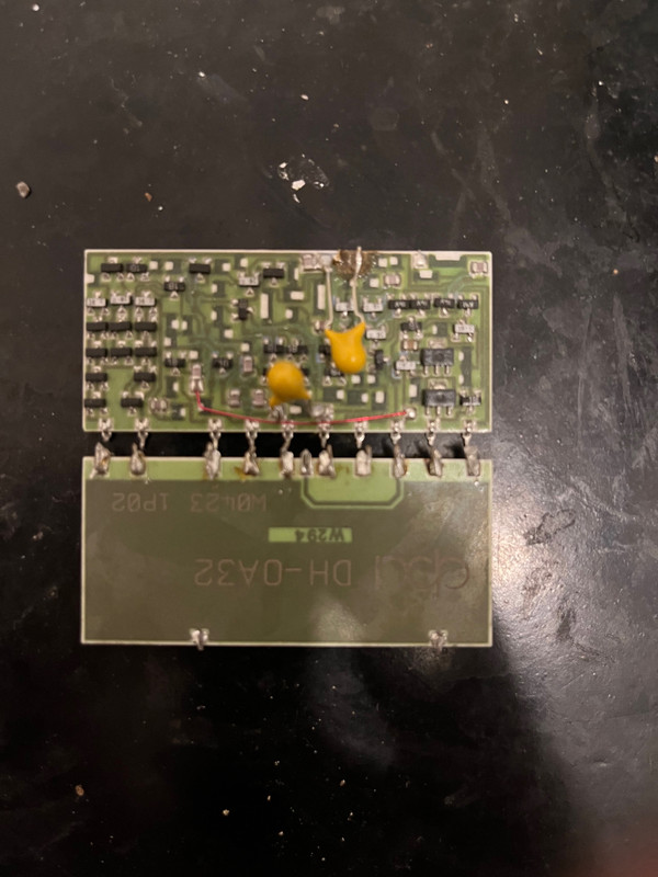
So after some considerable delay and thanks to @40imp I'm almost ready to transplant a pair of DH-OA32 op-amps into my pre-amp's phonostage that currently has a broken solder pad on one of the boards.
Is there a specific bias that they run best at?
With pins left to right I measure:
1 20.2v
2 20.2v
3 L 2.5v | R 0.5-1v* || Line stage = L 0v | R 0v
4 -18.4v
5 -18.4v
6
7 L -11.9v | R -11.8v
8 L -12.5v | R -13.2v
9
10
It also has what looks like hot glue underneath the boards, has anyone got any tips to remove or weaken this bond?
martin clark
pinko bodger
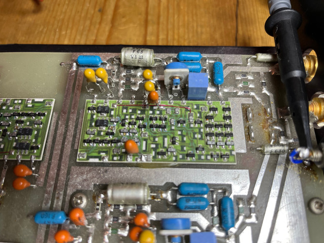
Re: adjustments - that blue pot, is DC offset control (the internal bias currents for the various stages are preset, and quite rich Class A for such a thing, esp output stage.)
What you call 'pin 3' reading left to right on your photo, is the Output pin; twiddle the blue pot to get close to 0v relative to the ground plane, there (As you note your line stage is set-up = '3 L 2.5v | R 0.5-1v* || Line stage = L 0v | R 0v' )
It is not critical, since the stages are only AC-coupled, but you might as well : D
Little update due - thanks for the help both of you.
The opamp board with the broken pad is out and new version installed. Initial power up gave me a shock as I was seeing a well off the mark 12-16v on pin 3 but a quick twist of the single turn variable resistor soon brought that down. Got it down to around +/-0.3v before attending to dinner and whilst cooking that seemed to go to 0.0xv by itself. Hooked it up without an input and nothing seems wrong yet.
I think it might be wise to leave the old working board in pending further tests. The hot glue did not seem melt on the hot air gun and forcing it felt like the board might well give in before the glue. Twisting might be a better an option but there is no clearance and that has the potential to take out the all the other components at the same time. Visually would be nice for them to match but if it ain't broken...
We shall see in testing.
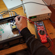
I've borrowed a function generator to test the balance between the two. Now I just need to borrow a suitable multimeter that can reliably measure down to 0.4mV to test the generator output before connecting it up. Hopefully tomorrow.
Is my laymen understanding right that a 50ohm output on this generator will lead to riaa discrepancies but should otherwise work, provided I don't overload it?
Here's the broken pad, the small dot about the size of the hair is all that is left of the connection. Is specialist pad repair a thing?
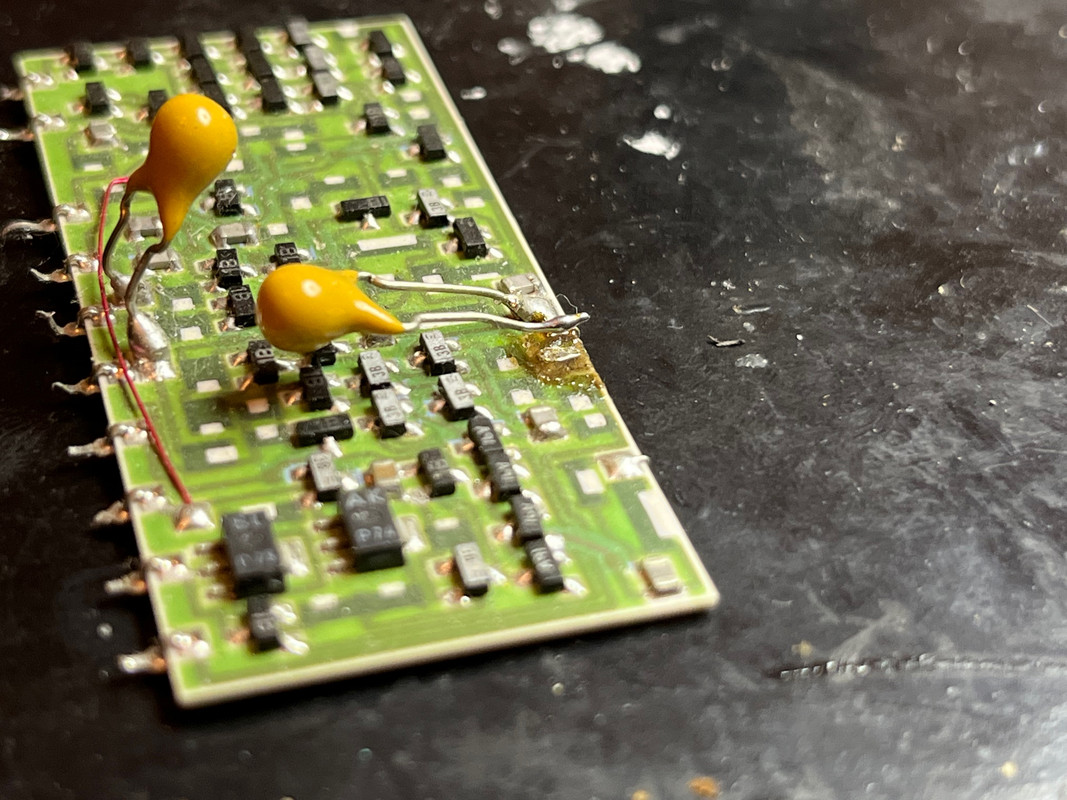
Interestingly the new board has an extra pinout:
Luckily we can see what it is connected too:
The opamp board with the broken pad is out and new version installed. Initial power up gave me a shock as I was seeing a well off the mark 12-16v on pin 3 but a quick twist of the single turn variable resistor soon brought that down. Got it down to around +/-0.3v before attending to dinner and whilst cooking that seemed to go to 0.0xv by itself. Hooked it up without an input and nothing seems wrong yet.
I think it might be wise to leave the old working board in pending further tests. The hot glue did not seem melt on the hot air gun and forcing it felt like the board might well give in before the glue. Twisting might be a better an option but there is no clearance and that has the potential to take out the all the other components at the same time. Visually would be nice for them to match but if it ain't broken...
We shall see in testing.
I've borrowed a function generator to test the balance between the two. Now I just need to borrow a suitable multimeter that can reliably measure down to 0.4mV to test the generator output before connecting it up. Hopefully tomorrow.
Is my laymen understanding right that a 50ohm output on this generator will lead to riaa discrepancies but should otherwise work, provided I don't overload it?
Here's the broken pad, the small dot about the size of the hair is all that is left of the connection. Is specialist pad repair a thing?
Interestingly the new board has an extra pinout:
Luckily we can see what it is connected too:
martin clark
pinko bodger
'Twisting might be a better an option'
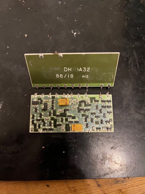
Don't do that - these are a ceramic substrate, likely to break.
Good job on the repair!.
If that 'broken pad is the connection on the right of the picture under the leg of the tantalum capacitor - I reckon that can be salvaged : )
Don't do that - these are a ceramic substrate, likely to break.
Good job on the repair!.
If that 'broken pad is the connection on the right of the picture under the leg of the tantalum capacitor - I reckon that can be salvaged : )
All done, both channels working, sounding ok and measuring around the same at the output considering the balance control. Bit of an earth loop hum on both channels but guessing that is the function generator.

Here's a better photo of the missing pad. There is a very small dot that I can make a connection to but it's not a secure joint in any way.
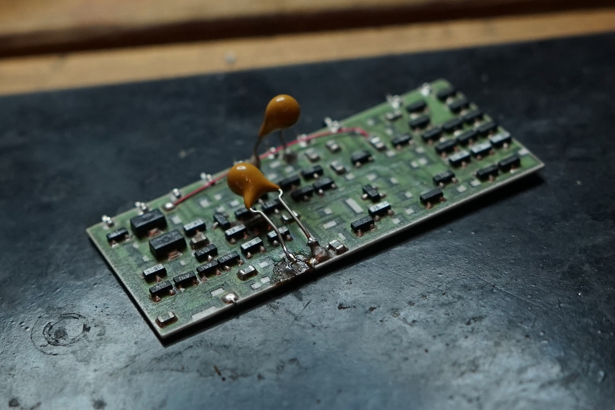
Here's a better photo of the missing pad. There is a very small dot that I can make a connection to but it's not a secure joint in any way.