advertisement


Can a Nait 3 be converted into a power amp?

windhoek

The Phoolosopher
I know Nait 3 amps can be converted to pre-amps, but I'd like to be able to convert mine into a poweramp. I want to do this because I need a poweramp to power the rear speakers in my 4.0 setup and to maintain surround sound cohesiveness, using my AVR's pre-amp (with it's room EQ, auto-setup etc) delivers best results. Fwiw, I've got a Nait XS powering the front speakers in poweramp mode via its Unity Gain input when I listen to surround sound but use it's pre-amp when I just want stereo.

Before I splash cash to buy a poweramp, if I can convert my Nait 3 and save money, that would be a win win! Can it be done and if yes, how can I do it?
 
Yes, it can be done - it involves cutting the four wires going from the PSU/power amp PCB to the preamp PCB, and fitting some new sockets. Then it can be used as a separate preamp/power amp - it could be put back to a regular integrated amp by using a short cable to link betwee these 2 new sockets. Not a very hard job by all accounts, as it was something that Naim dealers were allowed to do themselves instead of sending it back to Naim.
 
Naim used to supply a kit for the conversion.
It consists of a 4 and 5 pin din socket, and the instructions. The din sockets are PCb mounted ones.

The job is a snip of 4 wires, and solder the sockets. You then have a 90 & 92 in one box.
I have pics of my 92 at home, but there are plenty on the tinternet.

Tbh, I enjoyed my 92 + cap into a 140. If your climbing the naim ladder that may be a better option, the 90 is considered a weak link?

Double post, takes me a long time to type ;-)

Just looked at the kit, there's 2 4 pin dins, and one 5 pin. 4 and 5 pin for the pre, 4 pin for the power amp
 
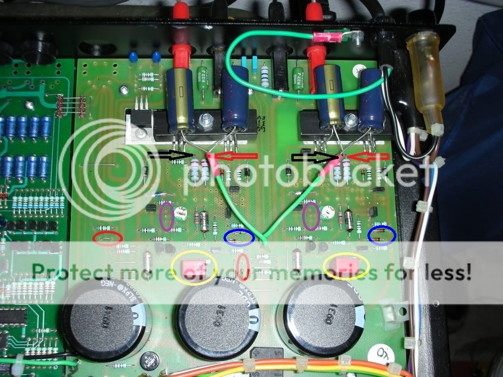
Below is a pic showing the inside of a Nait 3. I've added a red arrow to indicate the four wires that need to be cut - is that correct?

Nait3Inside_zpsfb2472e1.jpg


Once I've done that, what else do I need to do? I ask because I'm not sure how it would be connected to my AVR, which has phono outputs and by cutting the four aforementioned wires, how does an input signal reach the poweramp section? Fwiw, the signal flow is:
OPPO 105 (RCA out)>Yamaha AVR (RCA in and RCA out via pre-outs)>Nait 3.
 
Yep, those are the four wires. If you don't want to use the proper PCB mount DIN sockets, you could bodge it by fitting 2 RCA sockets where the plastic blanking plugs are on the rear panel. As for which wire is which, there is L, R, Ground and +24V (for the preamp section). You should be able to see which is which by following the PCB tracks around to see where they go - the 4 pin DIN input would be a good place to start tracking from (i.e. the space for a 4 pin DIN socket on the power amp board), unless someone on PFM can post up which is which (I would help but sold my Nait 3 a few months back)
 
...although you can find a really good power amp like the NAP140 for about £300 or maybe a bit less, and the Nait 3 would sell at £250-260, so once you've factored in the faff and butchery I reckon your best option is to buy a power amp, you'd get a big upgrade for not a lot of money at all.
 
I thought about buying a 140, but it looks like it's got a volume control and I want a poweramp without a volume control because my AVR will do that; which means the front and rear speakers' volumes go up in sync with each other. If the 140 doesn't have a volume control, that might well be perfect for my needs.

I've got an RCA-5 pin din cable already, would that do as far as cables are needed? If yes, I presume it just connects to any Din input? Or would it need to connect to one of the two hidden sockets on the rear?
 
No, the knob on the 140 is the on/off switch not a volume control :) Same with all the other older Naim NAP power amps that have knobs.

Re. cable, what DIN conector does it have? The NAP140 has a 4 pin connector, not compatible with the 5 pin style used on the Nait 3.
 
Ah, I meant I could use the RCA-5 pin Din cable with the Nait 3. Would that do the job? Or would any of the hidden sockets needs to be connected in some way?

That's great news about the 140! A friend said it would be better, but I discounted it thinking it had a volume knob, doh!
 
You could use the Nait 3 as a temporary power amp, yeah - just pop the signal into one of the DIN inputs and set the volume knob to an appropriate level, and leave it there.
 
So, by converting the Nait to a poweramp (by cutting the four wires), all I'd need to do is connect it to my AVR using one of the four 5-pin din inputs and use my AVR to control the volume. Is that correct? And, by cutting the wires, the Nait's volume control will be defunct, is that also correct (I hope that's the case)?
 
No - I meant you can use the Nait 3 as it is for now as a temporary measure without converting it or cutting any wires. The 5 pin DIN inputs are on the preamp side, it will still work as an integrated amp with volume control. Just leave the voluem control alone once it's adjusted to the right level and it will work fine for what you need.

Do not cut the PCB wires unless you know which wires are which and you have the sockets needed to finish the job off.

Once you have a NAP140 or similar, you'll also need to get a 2RCA to 4 pin DIN cable.
 
I see what you mean; that's what I've been doing already with the Nait 3. I just wondered whether I could make into a poweramp and bypass it's pre-amp section altogether because as things stand at present, the audio for the rear speakers is being processed by two pre-amps - my AVR's and the Nait's.

Leaving the Nap 140 idea aside for the time being, if I do cut the four wires, what else do I need to do? How will audio signals reach the power section of the Nait?
 
I think the best Idea here would involve a bit more disassembly.
That way, It can be put back as Naim intended with resale value intact.

Cut the 4 lines from the power to pre boards
Remove the pre board (you will need a circlip tool for the volume/balance
Desolder and lift the signal pins from centre of the two phono sockets on the left
refit the pre board
Get 3 lengths of wire(red/white/green whatever), plait them together
Solder one end to the phono sockets left/right/ground
Solder the other ends to the poweramp board left/right/ground
Refit lid and job done

The phono sockets on the back panel are now directly connected to the poweramp board
This way the rear panel with the markings is not damaged still looks as Naim intended.

I have piccys I can fart about with if you need something a bit more `visual`
and which are left/right/24v/ground wires on the power board

have fun
Justin

EDIT:
Actually, I dont think you need to remove the pre board at all!!
by the phono sockets to the left are a set of connectors for the MM/MC boards
left and right of these are two wire links.
You must cut these two links to fit the boards so,

Cut the 24v and left/right wires between the pre/power boards
cut these two links
a wire from each of these links to the left/right on the power board and BINGO!!
 
I was about to reply that the job of removing the pre-board doesn't seem too complicated and then you go and make things even simpler! :)

The two wire links at the phono stage are already cut (I did it when I added 522mm phono stages, although the phono stages are now out of there), so it looks like all I need to do is cut the four wire links between pre and power boards and connect wires directly from the RCA inputs to the power amp bit.

The only question is, where do I connect the lengths of wire on the power board and how will I know which wire connects to which strip on the power PCB?
 
If you have a multimeter or continuity tester it wont be a problem, Ive just been farting about with paint and come up with this.. (Excuse the teddyregs)

14930075


Well Ipernity has *ucked me again, cannot find the sharing pictures doodad:(

On the power board are two 10uF tants, little blue blobs!
with your multimeter you should be able to beep test from these to the wire links which one is for left and right looking at the markings on the back panel
I will try to find a link to a piccy
 
Does the pic below help? Fwiw, I never added the arrows or circles/ ellipses which are visible in the pic and sadly, don't have a multi-meter.

NAIT3-1.jpg
 
I was just looking at that piccy a minute ago;)
The two red circles are where you would find the 10uF coupling tants, you should be able to beep test which is which on the wire links

You need to cut 3 wires between the pre/power boards
Left Right and the 24v feed

The Ground which NEEDS be left connected can be found by testing the outer gold on the phono connectors and the wire links

EDIT:
Just spotted you dont have a multimeter, they are very cheap these days starting with summat like this

http://www.maplin.co.uk/domestic-multimeter-37279#questions

They are quite handy when you have one, this will test a fuse and will be fine for this job!
 
Mmm, without a multimeter, it seems a bit trickier. I do understand what needs to be done though.

1. Identify and keep ground link between pre and power boards.
2. Cut the three remaining wire links.
3. Attach wires to the bits where the red circles are located - the left bit for the right channel and the right bit for the left channel (as the Nait's speaker terminals are back to front).
4. Connect up and enjoy :)


advertisement


Back
Top