advertisement


Audionet ART v2 vintage CD player - PSU problems

Dowser

Learning to bodge again..
I recently bought one of the above from a local auction site - sold as faulty and not reading discs, fair enough, uses a CDM 12.1/VAM 1202 mech. Popped it open before doing anything and it has bigger problems than not reading discs! Someone has had a go at repairing an Analogue power supply fault...badly :) Parts missing & tracks broken, not properly re-assembled.

Shame, I'd like to listen to it. Contacted seller and said either return for full refund, or give me 50% of purchase price back - he chose the latter, and I'm now wondering if I bit off more than I can chew o_O

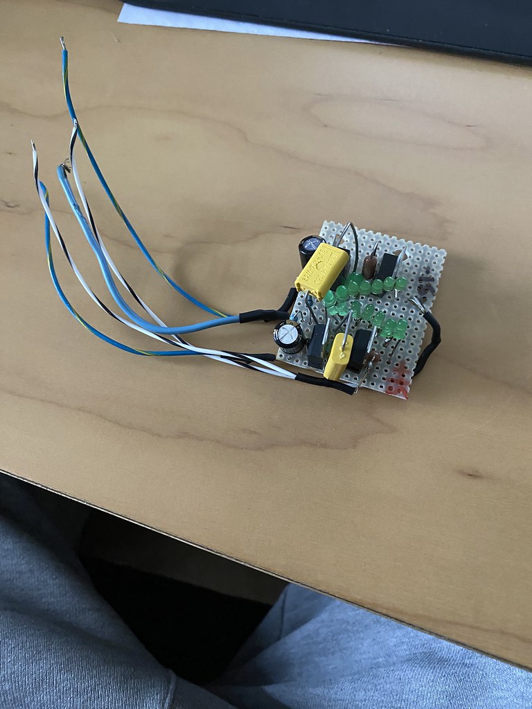
Photos below - after cleaning it up a bit and making sure of no shorts I powered it up - +/- 22v smoothed goes into the regulator stage - -15v comes out from untouched channel, nothing from + rail due to missing transistor. Working rail uses a FZT753 PNP, it's NPN equivalent (missing) is an FZT653. There's also a 680 ohm surface mount resistor missing.

I can source these parts no issue, bigger concern are any broken tracks and how to correctly re-wire things - does anyone have any knowledge of a +/- PSU topology using these transistors? Thanks 👍

Anyhow, photos;

First clue all was not well
53574188382_5792f22ce6_b.jpg


Eek!
53575379019_764519a62e_b.jpg


Looking better after a clean up with alcohol and a soft toothbrush
53575261918_17c256fe98_b.jpg

53575378989_abf0000e13_b.jpg


Hopefully I can repair it, otherwise I need a cct for a decent +/- 15v supply using +/-22v as source :)

Many thanks, Richard
 
Using a magnifier you most probably will find out the missing tracks. Using a small gauge wire which can easily be flatten you can repair them.
Just be patient, if you can't find the schematics and you think it's necessary you can reverse engineer the whole analogue power supply.
Ain't no use trying to find a schematic with this exact transistor, it's better to have a clue what kind of supply it is: regulator based, cap multiplier, opa shunt, or whatever.

With faulty items it's hit or miss thing, could be a simple fuse or the whole thing burned beyond repair. Good luck
 
Last edited:
Thanks, yeah, I can replace missing components and repair tracks with litz wire, guess I need to check first if the small smt transistors before the regulator are ok
 
Hmm - spent some more time stripping this down to try and identify missing track locations...no way basically. Photos below, I'm now looking for a compact, high quality +/- 15v regulator :) I open a separate thread.

Started with what previous attempted repairer should have done, remove board and caps to give some space;
53576772926_513bf4fe80_b.jpg
53575908062_48cfb4c1e0_b.jpg


Tried scratching tracks, and removing one of the SMT transistors...no good, multi layered PCB and dodgy top surface tracks;
53577097204_975b60408c_b.jpg


I measured the caps I removed - pretty tired - all high value ones 20% down and high ESR.
 
One side looks to be a mirror image of the other - could you use that to trace the broken traces along with some pinouts?

Failing that, you could rig up a simple 7815/7915 circuit just to get you going?
 
One side looks to be a mirror image of the other - could you use that to trace the broken traces along with some pinouts?

Failing that, you could rig up a simple 7815/7915 circuit just to get you going?
Thanks Fran - it's bipolar, tracks are slightly different, and completely untraceable...a shame.

I've got the board highlighted by Mike on the way.

I'm going to fit this in the interim :)
53578507001_e2ffa62d9e_b.jpg
 
:)

53593521945_414a587e0d_b.jpg


Stupid (well, maybe good design, no good for a bodger like me) PCB has an earth plane top and bottom of PCB...and tracks are just printed, they must actually be in the middle of the multi-layered PCB. Ended up having to remove SMT components to disable what was left of original PSU;

53593395214_0e7a9f8c81_b.jpg


Planned to have a go at cleaning/relubricating CDM 12.1 mech today...but just picked up a dCS Purcell to go with my Delius, so much listening to do...will await the replacement mech from Donberg :D

Richard
Hi, Could Audionet help?
 
Hi, Could Audionet help?
No response to an email, I guess it’s too old for them.

Love the Dremel work sir, a man after my own heart
fat lot of good it did me, except to learn there’s a top ground plane :)

Donberg we’re out stock of 12.1 mechs, replacement on its way now. Weird fault now, sometimes laser sled motor runs it to outside edge, sometimes not, but disc never spins (but laser lights up weakly). I hope it’s laser related, hopefully a duff ribbon or other cable…but the stock mech is seriously glued in place, looks like I need to transfer the internals!
 
That’s disappointing, I really wanted one of those toploader’s😮 They’re beautiful bits of kit. Hopefully they might reply at some stage 😞
 
Finally coming back to this - the replacement lasers from Donberg never arrived - one issue I had with them is they never give a tracking number, first time I've actually had problems, they were communicative, but couldn't help. I ended up disputing the transaction with credit card company, 1 day before the refund Donberg confirms they just received the item returned - I paid an extra €17 for a tracking shipment and they arrived last week.

But damn, units are subtlety different - VAM1201/11 is the original, VAM1202/12 is the replacement 12.1 mech from Donberg - see piccies below, cct board is laid out a little different, but has same number/value of components on a quick check. Big difference is the laser lens itself - straight fitment on original, round fitment on replacement.

Only found this out by removing the original laser - again damn, Audionet super-glued it into place, wow! Managed to crack it off without damage though.

I've since found a couple of German sources for replacement mechs with correct laser fitment, so intend to order one to try.

Symptom though was simply no action from mech - winding laser until out to middle and power it on, laser sled does not move. Before chucking it all back together and going for a motorbike ride in the sun, decided to measure laser sled motor resistance - now it gets weirder; item I had fitted measures 23 meg across terminals! Original measures 18 ohms, more like it. Then I grab another of the replacements from Donberg - it reads 25Kohm!

Guess as a next step, now I have stripped original laser from it's superglue, is to refit it and measure things properly - but can't be arsed today, twisty roads are calling before a swim in the lake :D

Does anyone have experience of round mounted and flat mounted laser units - are they compatible? Pictures below!

Many thanks, Richard

Original mech super-glued;
53795242630_74a6ffcc15_b.jpg

53795141349_62f5976251_b.jpg

53794831061_68cf6eaa15_b.jpg


Slightly different PCB layout, but pretty much the same I think;
53795141344_a034987b20_b.jpg


Difference is here, where the laser diode mounts - different diode assemblies, no idea of they are compatible?;
53793887197_8b27a714ae_b.jpg


Thanks again
 
Any chance there's a anti static solder blob still on the new board?
Was the sled switch connected when you tested?


advertisement


Back
Top