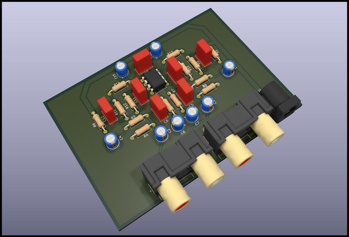
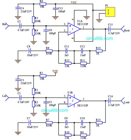
Would any of the kind folk here be willing to assist in generating PCB files from a schematic that I could then send off to a supplier for a small quantity? Nothing major, just a small NE5532-based phono stage that I'd like to use in a couple of projects. Happy to compensate for your time. I appreciate there are free PCB design programs out there but I am not yet versed in their use. Thanks!
You are using an out of date browser. It may not display this or other websites correctly.
You should upgrade or use an alternative browser.
You should upgrade or use an alternative browser.
Assistance generating PCB files from a schematic?
- Thread starter hi-fi132
- Start date
Arkless Electronics
Trade: Amp design and repairs.
But you just need to press the Autoroute button....
How big a schematic are we talking about? Are all the parts fully specified?
31 components; 14 resistors, 15 capacitors, 2 8-pin ICs. All specified in the schematic and I have a PCB layout PDF too. I just hate using veroboard
david ellwood
Kirabosi Kognoscente
Come on then show us a picture
Come on then show us a picture
It won't let me post an image for some reason, fails with an error. If you can PM me an eMail address I'll send you the files.
david ellwood
Kirabosi Kognoscente
Hopefully this works. Tried a direct link from my own site but was getting a javascript error.
david ellwood
Kirabosi Kognoscente
Spotty Dog!
mansr
Objectionist
The values are specified. The packages are not. Do you want through-hole or surface mount? Any size or other constraints on the PCB?31 components; 14 resistors, 15 capacitors, 2 8-pin ICs. All specified in the schematic and I have a PCB layout PDF too. I just hate using veroboard
The values are specified. The packages are not. Do you want through-hole or surface mount? Any size or other constraints on the PCB?
Ah yes, forgot about packages. All through-hole. No size constraints really, can't imagine it would end up being massive. 3 mm mounting holes in the corners would be nice.
mansr
Objectionist
Through-hole parts come in many sizes too. Do you have specific part numbers in mind? You might want to head over to https://octopart.com/bom-tool and make a list of exactly which parts you want to use. Then it will be easy to pick the correct footprint for the PCB.Ah yes, forgot about packages. All through-hole. No size constraints really, can't imagine it would end up being massive. 3 mm mounting holes in the corners would be nice.
Through-hole parts come in many sizes too. Do you have specific part numbers in mind? You might want to head over to https://octopart.com/bom-tool and make a list of exactly which parts you want to use. Then it will be easy to pick the correct footprint for the PCB.
I don't have specific parts in mind though it won't be anything extravagant, it's just a simple MM preamp for embedding into a couple of projects. The one I did build on verroboard (which sounds great) just used parts laying around, built on a board with holes on a 0.1 inch pitch. I appreciate that doesn't help with lead spacing etc, but are there 'standards' or a 'happy medium' commonly used in simple PCB design?
Spotty Dog!
A phrase I must admit I hadn't heard before, though apparently predominantly used in the north east and as I'm from the south west we have far too many of our own. The urban dictionary gave some hilarious suggestions for related phrases, well worth a look.
mansr
Objectionist
Resistors come in a few common sizes, and there's always some flexibility with through-hole. For the non-electrolytic capacitors, you have a choice of ceramic or film. Do you still have parts lying around, or would you be buying new?I don't have specific parts in mind though it won't be anything extravagant, it's just a simple MM preamp for embedding into a couple of projects. The one I did build on verroboard (which sounds great) just used parts laying around, built on a board with holes on a 0.1 inch pitch. I appreciate that doesn't help with lead spacing etc, but are there 'standards' or a 'happy medium' commonly used in simple PCB design?
Then there's the connectors, and there's endless variation there. I'm guessing regular barrel jack for power and RCAs for signal.
mansr
Objectionist
Yes, I guess that should cover most commonly found parts.10mm for resistors, 2.5mm for elec, 5mm for equalisation caps, standard dip for the 5532 and you will be fairly safe to go from anyone’s odds and sods bin.
10mm for resistors, 2.5mm for elec, 5mm for equalisation caps, standard dip for the 5532 and you will be fairly safe to go from anyone’s odds and sods bin.
Spot on based on the components used on previous board. Barrel jack for power would be ideal for future uses. The boards are intended to be used with other modules so I hadn't considered audio connectors. If there's a standard for generic board mounted RCA pairs that would be good, but otherwise they could be brought out anywhere as they'll most likely be wired directly to other things anyway.
Such a project is the perfect excuse for trying ones first steps with Kicad or the like. Once found out how to draw a circuit it will be of great benefit for future projects. Even small adapter PCBs for parts with very small and narrow legs are doable for small money and less time than fiddling around with the solder iron to attach cables to them, to name just one example - at least that's my experience. Also there is software to design for vero boards, so no need to wait for PCBs being shipped in case of such a simple curcuit.