advertisement


Another Leak Stereo 20

It looks like you've installed a couple of the black electrolytics with the wrong polarity. Cross reference against the one I restored.
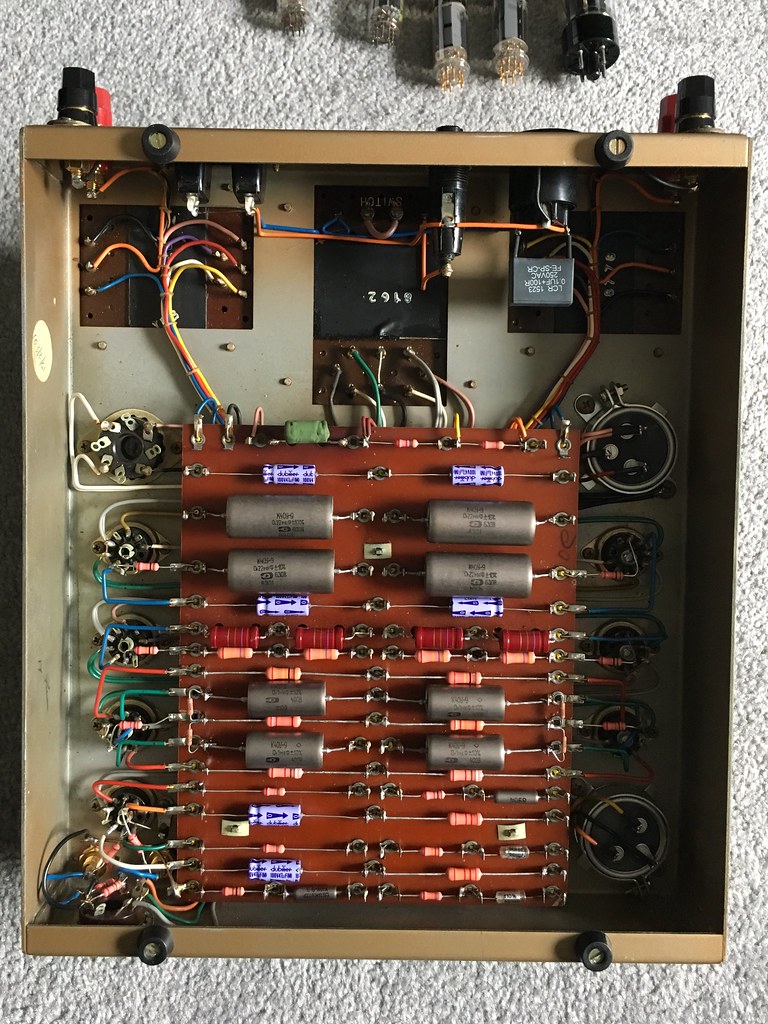
Nice spot Mike! Will correct tomorrow. Already checked the impedance selector plugs but will solder some wire across them while I've got the soldering iron out.

TS
 
Great work, looks really neat.

Notice you’ve upped the values from 47uF to 100uF of C7 and C8 - any advantage to doing that?
 
Great work, looks really neat.

Notice you’ve upped the values from 47uF to 100uF of C7 and C8 - any advantage to doing that?
I just went with the values Mike P used for the amp he rebuilt for me. Not sure what, if any advantages there are to upping these values.
 
Another update.

Put the caps the right way round after checking they were still reading 100uF on my DMM. Soldered the impedance plugs. Issue remains the same.

Swapped the inputs, issue stayed with the RH speaker, swapped the outputs, issue moves to the LH speaker. Tried swapping valves around, issue remains.

Given the amp a good visual inspection & resoldered a lot of components, issue remains

Checking values of components in situ cross referencing with the Mike P amp. Getting odd readings across the 12K resistors at R18. On the Mike P amp they are both reading 100R in situ. In my amp R18 LH is reading 100R, R18 RH is reading 12K. Any thoughts?

Cheers

TS
 
Has cleaned up nicely though...

20230902-142225.jpg


TS
 
Any thoughts?

Post another pic of the amp so we can see where you are right now. A lot of stuff was missing in the earlier pic, e.g. one output transformer wasn’t wired in.

For reference here’s a pic of my old one:

47568743462_0a268f2871_b.jpg


Not everything is visible in this pic (e.g. around the octal connector) but it is fairly good, so if you could post a pic below from the same orientation and perspective it might make checking wiring etc easier.
 
This a pic of the amp taken just now. I did have a suppressor cap fitted but I've removed it again so I could get to the wiring around the output transformer.

20230902-165555.jpg


TS
 
Good evening Tony,

Check the wiring to the can capacitor bottom right, are the yellow/ orange wires back to front?

Regards

Richard
 
I’m really struggling to spot anything wrong. Do you have a wire connected to the top right tag on the board, the one next to the big chassis can cap? It is likely just out of view in the pic, but I can’t see it.

Based on my experience with the TL12 Plus the next thing I’d study is every single fork connector in the McMurdo 9 pin valve bases. It took me so long to track down my issue to a broken pin fork in one of the ECC81 valve bases. I’d actually made no mistakes, both amps looked identical, yet one didn’t work! You need a magnifying glass and to poke both sides of each fork with a pin to make sure they move as one (i.e. aren’t broken!).

Whilst it is really not the answer you want I’d also figure out (I don’t know myself) how to check the output transformers, i.e. make certain the one on the silent side measures the same as the one on the side that makes sound. I am surprised you are getting nothing, even in a fault condition I’d expect some low-level noise.

PS The can cap is (IIRC) 32uF/0/32uF, so as long as the black ground is right it doesn’t matter which colour goes where.
 
I think checking for continuity across the output transformer windings would be a good next move. You have the other channel and the amp I did for cross referencing.
 
I’m really struggling to spot anything wrong. Do you have a wire connected to the top right tag on the board, the one next to the big chassis can cap? It is likely just out of view in the pic, but I can’t see it.

Based on my experience with the TL12 Plus the next thing I’d study is every single fork connector in the McMurdo 9 pin valve bases. It took me so long to track down my issue to a broken pin fork in one of the ECC81 valve bases. I’d actually made no mistakes, both amps looked identical, yet one didn’t work! You need a magnifying glass and to poke both sides of each fork with a pin to make sure they move as one (i.e. aren’t broken!)

Yes Tony, the tag at top right corner is connected, just out of sight. Will have a look at the valve bases next.
 
I think checking for continuity across the output transformer windings would be a good next move. You have the other channel and the amp I did for cross referencing.

Really hope it isn't a faulty output transformer but I'm beginning to think (dread) that it might be.
 
Sunday update.

Good news first. Continuity checks on output transformers were encouraging, couldn't find any differences between Left & Right. Still, that little niggle in the back of my mind...
Decided to remove transformers & swap them over just to be sure. Phew, problem stays on the RH channel, no music just a constant 50 hZ hum.

Bad news. Now I'm completely stumped! Can't find any broken forks in the valve bases so I'm completely out of ideas.

Should reiterate, I'm still getting the odd readings across the 12K resistors at R18, maybe a clue to those more knowledgeable than me (most).

Once again, thanks for the help.

TS

Sounds like an open cct resistor somewhere that is also somehow in parallel with R18 - sorry not familiar with the cct, but if you have a diagram it should be possible to work out.

good luck
 
Check R4? Check the soldering and the reading across them.

Personally I'd not trust those two electrolytics you installed backwards and I'd replace them.
I have been wondering whether those caps I installed backwards could be an issue. Sadly they came in a pack of five so I only have one spare. Will order some more. Will also take a look at R4.

Cheers Mike

TS
 
Sounds like an open cct resistor somewhere that is also somehow in parallel with R18 - sorry not familiar with the cct, but if you have a diagram it should be possible to work out.

good luck
Was going to take some time today to study the circuit diagram, see if I can learn how to interpret it a bit better. Was able to read circuit diagams & read the markings on resistors when I was a [much[ younger man. Sadly those skills aren't like riding a bike!

TS
 
Measure across the 100R resistor, do you get 100R?. If so then there is a break somewhere in the loop. It could be open circuit in the transformer secondary but very unlikely. More like a ground wire is broken or left off somewhere.


advertisement


Back
Top