advertisement


A valve line pre amp for the DIY fishy

Slight update is that I've been able to change my transformer for one with a center tapped 190v-0v-190v secondary. So I think this will give me (190 x 1.414) 269v into the EZ80 rectifier. I'm struggling to figure out what the voltage drop will be, but will soon find out once I've started building it. Assuming my output voltage needs adjusting, would it be best to do this by changing R15?

My other question for now is about grounding. Would it be best to
1. ground everything direct to a bolt though the chassis as a star ground?
2. keep my ground separate to the chassis ground. And have chassis connected to mains earth?
3. Same as above but connect chassis ground to to my separate circuit ground via a resistor?

I've got 3 different books I'm reading alongside this project which suggest each of these, just trying to pick which will be best.
There should be two separate gnds, the chassis earth and the PSU gnd.

This is the link for Al's pictures https://photos.app.goo.gl/HW0rZ7hq29swMUY13

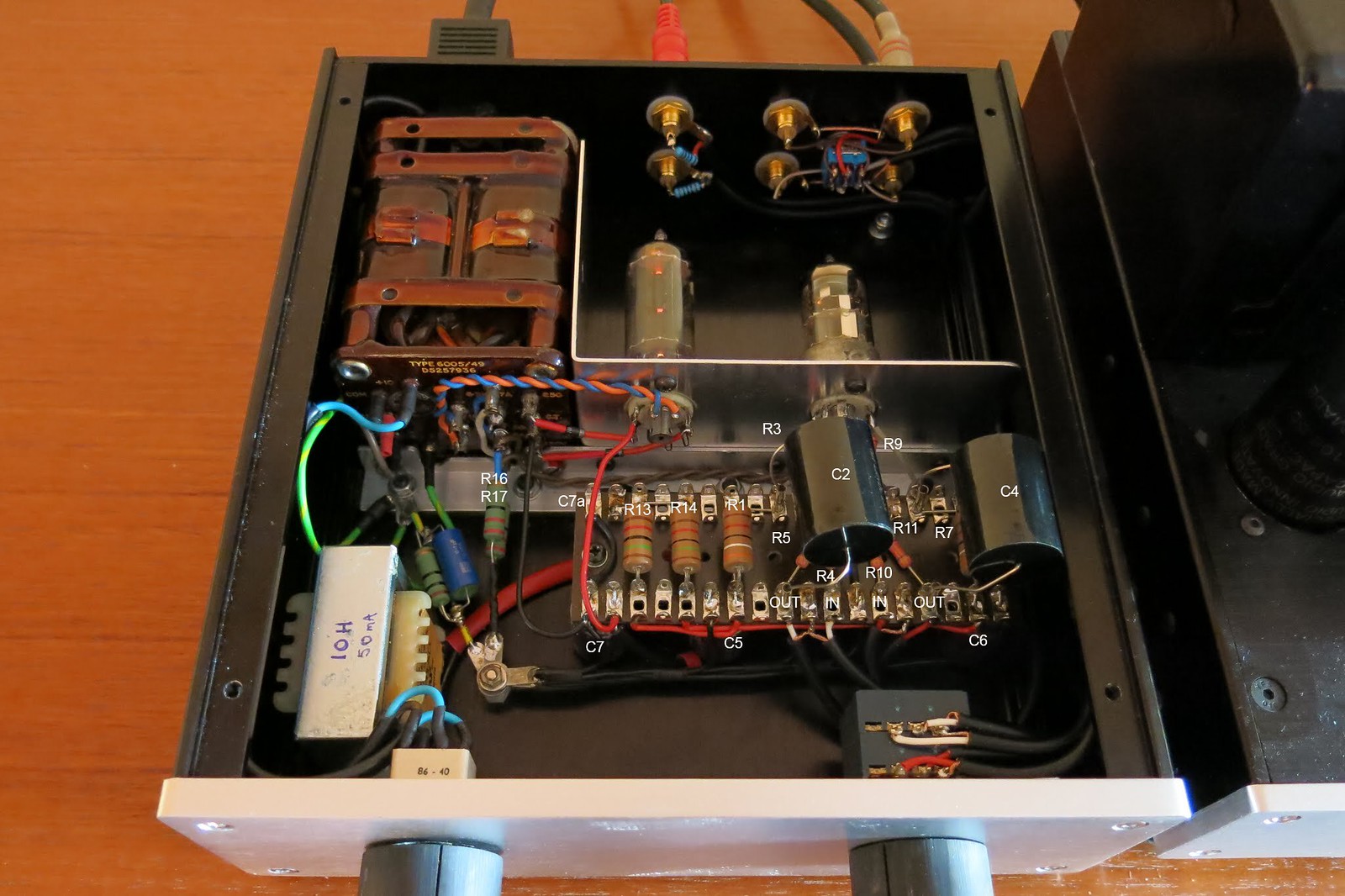
Note that the choke is connected between the +ive pins of C7 and C7a, again under the tag board. C7a was added as extra smoothing after the choke.

PSU GND
Have a good look at the picture. Note that the tags for the PSU gnd are isolated from the chassis gnd being mounted on a tag board.

53081867529_a23d8b5a3f_o by Garf Arf, on Flickr

The PSU gnd has separate connections (black wires at the bottom on the picture):
  1. all the -ive pins on the 47uf PSU caps (C7, C5, C6), bar between the first and second caps (see the black wire on the left of the tag board between the -ive pins of caps C7 and C7a, slightly hidden under the red wire from the rectifier valve socket),
  2. the centre of the valve socket for the E88CC valve from there to pin 9 on the valve base (solid wire across the tag board and then black wire to the middle turret of the valve base, and then to pin 9),
  3. from the ends of the cathode resistors and capacitors which are under the tag board. Black wires from tag 5 and tag 9 (counting right to left), bottom of the tag board to PSU gnd. Also note, that the signal gnds of the input and output wires connect at these points on the tag board and not directly to the PSU gnd.
  4. from the AC heater wires, via two, one each side, 22R resistors (grey)

CHASSIS EARTH
This is Al's picture of his build and you can see the 10R resistor on the left, by the choke, with a blue 0.1uF cap across it. That is the connection between the PSU gnd and the chassis earth. This resistor/cap combo reduces "hum" in the pre-amp.

IMG_7915-labels by Garf Arf, on Flickr

Obvs, the chassis earth has three connections, one to the incoming mains earth wire, one to the metal chassis and one to the PSU gnd via a 10R resistor. In Al's picture there is a connection from the chassis earth to a transformer screen.


In fact there is one more gnd connection to consider and that is from the centre tap of the HT transformer. If you look very closely at Al's picture there is a thin black wire loop from the RHS of the transformer to the -ive pin of C7. That is where the CT has to be connected and not to the PSU or the chassis gnd.
 
Last edited:
Big thanks @chiily , that's a great help.
I'll download Duncan's PSU software and have a play around tonight
No problem at all, ask away. :)

I read and re-read this thread many times, digging out the gems of information between the posters, esp Al and Jez, years of experience that novices like me have to learn and understand. I thinking grounding is one of those subjects that one can read about in books, but only experience can really apply it to circuits correctly.
 
2oTjeBD

2oTjeBD

https://flic.kr/p/2oTjeBD
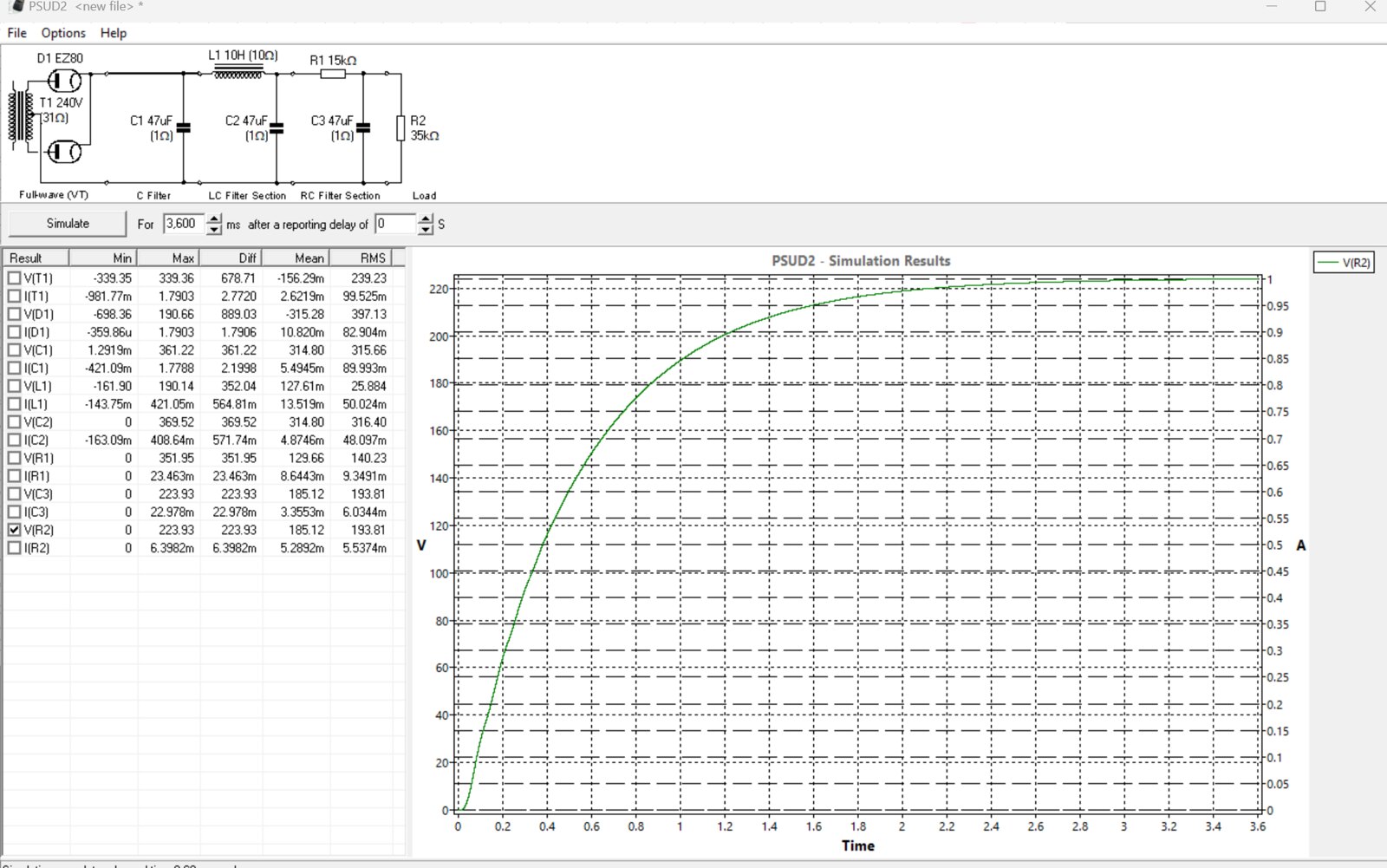
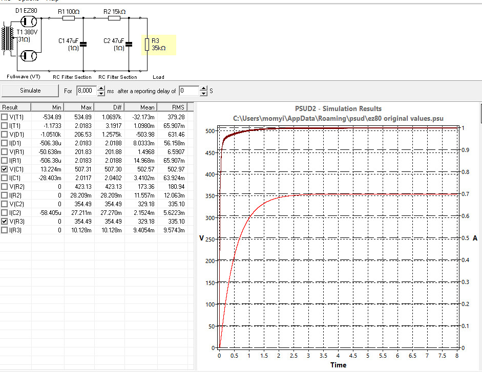
Playing around with Duncan's PSU designer I've got the original design of the PSU in just with EZ80 rectification and my 190v-0-190v transformer. I'm not sure what the transformer resistance should be so copied your example of 31R @chiily. Same for the load resistance, copied yours of 35k.

Should I now be increasing the value of R2 until the Max voltage at R3 is 250v? Earlier in the thread Jez mentioned the top of C7 (C1 in this simulation) should be 340v. Does this remain important?

Is there anything else I should be considering? I assume it'll tell me if I'm about to blow something up, but where does it show the ripple?
 
Let me post the picture. Just copy and paste the BB code...

Screenshot 2023-08-02 190329 by Adam Peacock, on Flickr

The resistance of the transformer was just as the PSU designed put in. The 35K was from the anode resistors and the valve resistance, seemed about right.

You should be aiming for about 66V at the anodes of each of the triodes, which would mean you would have to change the values of R15 and it's opposite to get down to the right voltage on the anodes.

I worked out that there is about 5.6mA current through each triode. In my build, using 5.6mA (which you should maintain), R1 (30kR) drops about 170V and R13 half that 85V. I would suggest working on achieving 66-70V on the triodes' anodes, with R1 at 30K, current at 5.6mA, by tweaking the value of R15, based on the voltage coming out of C7. I would suggest you do that by building it and measuring!

The ripple value I measured at the anode of each triode, though by delaying the sim's start time to when the voltage is stable, the Y axis will auto range to capture the ripple. So set the delay to 4 secs, and re-run the sim.
 
What I like about a project like this is it helps me realise all the stuff I don't know. The only thing I'm waiting to arrive is my transformer now, and desperate to get hands on and starting building, measuring and tweaking rather than getting more and more confused in theory.

After hours of playing around last night on Duncans PSU designer trying to get something even nearly right; I think I've misunderstood how to enter the value of my transformer. For a 190-0-190 transformer I'd totaled these for a 380V transformer. Looking at the voltages coming out, Am I now right in saying I should of entered 190V for the transformer output and let the software work it out for me?

I'll put some photo's up soon of my progress with the chassis work. Hopefully to show, whilst electronically I might be struggling, at least it'll make a nice ornament if all else fails.
 
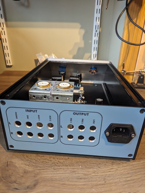
A few photos of where I've got to. I'm still waiting on my transformer and RCA sockets. For now, I've stood the tag boards on plastic bases so I can play around with positioning. I'm quite pleased with the input/output labelling on the back panel, achieved with water slide transfers. I had to paint the back panel a lighter colour though as the transfers didn't show up with a black background. I'd planned on replacing the volume and selector switch decals as well on the front panel, but I think the originals must of been etched or laser printed on as I can't remove them. If it takes much longer for my transformer to arrive, and I get impatient, I might try sanding it down and attempt a brushed finish.

Arkless preamp build by Adam Peacock, on Flickr

Arkless preamp build by Adam Peacock, on Flickr

Arkless preamp build by Adam Peacock, on Flickr
 
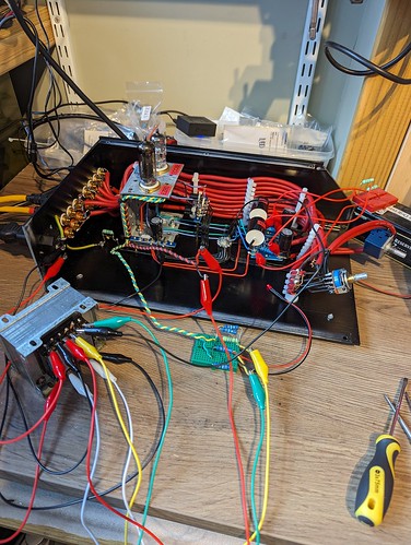
I've got everything all together now and it works! I have music, and no explosions yet
  • At R1/R7 I've got 246v, where 250v is recommended.
  • At the Anode I've got 70v where 66v is recommended.
  • At the Cathode I've got 1.3v, which is right.
So I'm 4v too low at R1/R7 and 4v too high at the Anode. How crucial are these voltages? Assume I should be looking to drop the value of R13 to get 250v top of R1, then increasing the value of R1 to get my voltage down to 6.6v at the Anode?.... Or leave it alone as it's close enough?

I've got quite a considerable hum through the speakers at the moment, though I still have a lot of the circuit connected up with crocodile clip leads, so hopefully that goes away once it's all in place.

Well done you!! We just need pictures now :)

For me those voltages are close enough, and they are all driven by your mains voltage. I found the voltages changed depending on the valve type.

Do make sure that you turn your amps off before turning the preamp off; heed Jez's warnings above, unless you are using the zener diodes in the cct.
 
Great, I'll get it all built up properly without playing around anymore with the resistor values. I haven't used the zener diodes, as I understood I could do without them when using a valve rectifier; however, the power amp I'll be using is designed to be left on all the time, which I find a bit odd anyway, so I'm not sure how I'll fit that in with the routine of turning this pre om first and off last. I might add the zeners back in just for peace of mind.

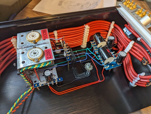
Here's a photo of how it looks at the moment. The case I bought has a sloping front which prevented me from moving the selector switch to the back near the inputs, so I ended up using a load of interconnect cable I had. For aesthetic reasons I had to sit the valves quite far back to avoid precut vents in the lid; I guess this could be the cause of the hum as I've had to run quite long leads from R1/R7 to the anode and also from R4/R10 to R3/R10, which at the valve base.

53128270843_f7aa510ca9.jpg
[url=https://flic.kr/p/2oWLgXH]PXL_20230819_145647665 by Adam Peacock, on Flickr[/URL]

[url=https://flic.kr/p/2oWKU3s]PXL_20230812_122611032 by Adam Peacock, on Flickr[/URL]
 
Well it's all together and looks nice, but it really hums. I've done a bit of poking around, nudging wires and connectors in the hope of hearing where the disturbance was coming from. I did find one bad solder joint, but it wasn't the cause. The hum is constant through the speakers and isn't affected by changing the volume, or input. I downloaded app which says the hum is 100Hz, though I don't know how reliable that is. Would the rectified live be at 100Hz? In which case should my first thing to investigate be the path of my B+ wires, which are the red wires.
Assuming that isn't the cause what areas of the circuit are most vulnerable to picking up hum and what would be a sensible order to work through to track down where it's coming from?
If it helps my wiring colours are; Twisted Red/Black is AC to the rectifier and also the front power on LED, Twister Green/Yellow are filaments, Red is B+, Black is Ground, Green is going to the Grid, Blue is used to go the Plate and also from the Cathode.
PXL_20230820_101032838 by Adam Peacock, on Flickr

[url=https://flic.kr/p/2oWQ6Zr]PXL_20230820_101052138 by Adam Peacock, on Flickr[/URL]
 
Ah ha, @Barrymagrec you're a genius! ... Or maybe just that, I'm not.

I'd forgotten my ground connection from C5. I'd counted out my star ground connection to have 2 spare, so should of been a clue that I had 4 unused tags. I'll get this wired up and have another go.
 
Just trying to orientate myself with your build.

The black and red twisted wires are the HT from the transformer to the rectifier? It looks to be routed quite close to the output sockets.

Has the transformer got a CT for the heater wires and the HT outputs? I can't quite figure out the tag board to the side of the transformer with the resistors in parallel. Could you explain a bit please?
 
Ok, with the missing ground connections now in place the major hum is cured.

Yes, @chiily the twisted black and red are between transformer HT and the rectifier. You're right, this was needlessly long and looping towards the output sockets. So I've shortened this as well.

and, yes there's a CT on the heater and HT secondaries. Both CT's are going to the base of C7 before connecting to ground. The tag board by the transformer has a 470R resistor to power front power indicator LED, but also two 0.39R resistors in parallel on either side of the heater wires to bring the filament voltage closer to 6.3v. I'd planned for just 0.39R either side but that didn't quite get me there; with 2 in parallel, it's spot on.

Here's an unsimplified schematic of my PSU. With the second 47uF capacitors now actually connected to ground, my measured output is 256V going into R1/R7

[url=https://flic.kr/p/2oWNHnF]PSU by Adam Peacock, on Flickr[/URL]


advertisement


Back
Top