
You are using an out of date browser. It may not display this or other websites correctly.
You should upgrade or use an alternative browser.
You should upgrade or use an alternative browser.
'80s Rega Planar 3 motor suspension screws
- Thread starter Seanm
- Start date
Craig B
Re:trophile
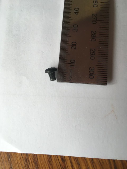
M3 x 5mm IIRC.
Rega 'To Replace Motor (Planar old style)' said:IMPORTANT - DO NOT OVER TIGHTEN! Motor mounting screws are made of plastic to avoid over tightening. Therefore the screws will not reach an "end stop" and so cannot be locked off. Continued tightening after a firm fit has been achieved will cause too much compression of the 'O' Ring, causing the laminate to buckle and the screws to strip or the screw head to break off.
- Fit both mounting screws so that only a small amount of thread is taken up and the motor mounting plate is still loose.
- Position the pulley slightly to the rear of the hole in the plinth and central in the left right plane.
- With one finger, push the pulley down into the hole so that the top of the pulley is just below the surface of the plinth and is leaning slightly towards the rear of the turntable.
- Whilst holding the pulley in this position, tighten both screws. The motor will then bounce into its correct position when finger pressure is released.
- The drive belt can now be fitted. This will draw the pulley into its final position
Last edited:
linnfomaniac83
I bet you can’t wheelie a unicycle!
Yep, and it might well be noisy too. Rega started using the sticky pads after changing to a newer, quieter motor iirc.Sean would need a new motor then, as the mounting flanges are intentionally bent down as hooks for the suspension O-ring. Pretty difficult to get these perfectly flat again.
Craig B
Re:trophile
Yes, and an improved AC PS board too.
Sean,
Whilst you have the motor cover off, you may want to have a look at the power dropping resistor in particular, as these can and do burn out over the years. The phase capacitor can go off as well.
Perhaps post a picture here, as, depending upon what board you have, there are a couple of options should it be in need of preventative maintenance or repair.
Last edited:
linnfomaniac83
I bet you can’t wheelie a unicycle!
The circuitry is incredibly simple but will run a little warm. It’ll probably be worth changing all the components out like for like, it won’t cost much and provided you’re handy with soldering, it won’t take long... then just replace the screw. An oil change and drive belt will then see it fit for service for a few years.Thanks all, very helpful as ever.
I had wondered about seeing to the board: I got the deck for a family member who lives quite far away so I’d like to future proof it as much as possible. I’ll post a photo tomorrow.
Last edited:
Seanm
pfm Member
Thanks very much Steve, really appreciate it, but I'd say it will only be a pound on eBay.If you don't have M3 or want to go out shopping PM me and I'll cut one to length and post it. Let me know head type, if hex or cheese easy, csk may be trickier.
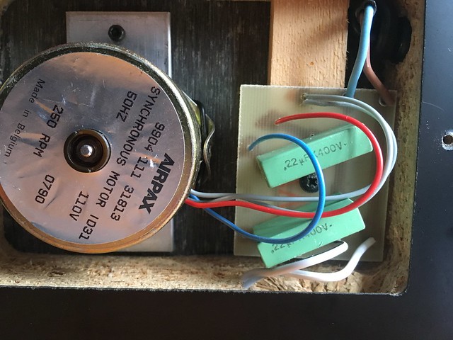
Here's a picture of the board and of the screw:
I might leave the electrics alone, I've only ever soldered speaker and RCA plugs. Sort of wish I'd left the suspension belt alone: motor was silent before, very noisy now - although hopefully once I get a proper screw in that will lessen (I've been improvising with a cartridge nut and bolt).
Is there a knack to centering the motor, and getting it to hang a decent distance from the deck?
Edit: looking at the picture I'd say my improvised bolt is probably touching the motor, source of the noise.
Craig B
Re:trophile
My post #2 above describes the motor alignment procedure. The key to correct alignment is that you don't tighten the screws until the motor has been pushed down into the described position. Also, the screws must only be nipped tight just enough to prevent the rubber O-ring from slipping out of alignment.
BTW, that circuit board is one of the later types that doesn't include the power dropping resistor of old. There is no need to change either capacitor out unless the deck starts running quite slowly and/or starts up running backwards. Chances are that it will outlive us all.
BTW, that circuit board is one of the later types that doesn't include the power dropping resistor of old. There is no need to change either capacitor out unless the deck starts running quite slowly and/or starts up running backwards. Chances are that it will outlive us all.