advertisement


250 speaker cable-a conundrum

diybry

pfm Member
In the interests of improving sound quality,I've been reading through the Fish archives, and of course the arguments rage back and forth regarding 'the best and most compatible' speaker cable for the NAP250.
The lack of any consensus is probably due to a combination of: (Not in any particular order) Music genre, presentation preference, speakers/equipment, hearing, room effects and size of wallet.
Acc to Naim, any cable should be of suitable capacitance and 3.5m min length to ensure stability.
This requirement for extended speaker cable lengths will surely increase the sonic signature of any cable chosen. (I guess) Not to mention the WAF.
My setup physically requires only 1m cable/speaker, but I have the prescribed 3.5m length.
Looking through the archives, I found this:

Originally Posted by LesW
16 turns of 1.2mm varnished copper wire wound on a 6mm drill
bit along with a 15R 2W resistor in parallel inserted into the centre.
Introduce this into the positive loudspeaker lead and you may then
use any combination/length of speaker lead that takes your fancy.
(Used in the NCC200s which are unconditionally stable)
Cue cries of anguish from the sheeple.


This gives the option of reduced spkr cable length, however what's the general opinion on the use of this circuit with 1m cable vs 3.5m of equivalent cable with regard to SQ?
 
This is how you make the output inductor and is what I fitted to my Avondale amps as Les states this makes the amp stable into any load and allows you to use and type or length of cable.
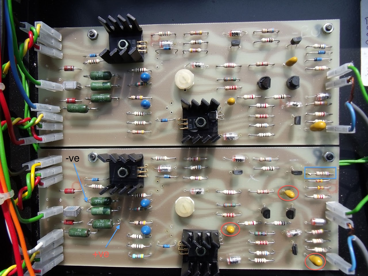
Never tried this with a NAIM 250 though?, if I was going to do it I would solder it inside the amp to the +ve output speaker terminal.
voyager 2 by 337alant, on Flickr

Alan
 
Thanks Alan, excellent photo, and exactly what I am planning, and yes I'll be putting them inside the 250, it's an easily reversible mod.
Surprised nobody else has chipped in on this one
bry
 
Thanks Alan, excellent photo, and exactly what I am planning, and yes I'll be putting them inside the 250, it's an easily reversible mod.
Surprised nobody else has chipped in on this one
bry
Because Alan has the best pictures. :)

Seriously though, his technique was used by all us NCC200 builders. It does take a couple of goes to keep the coils tight and the tension just right.

Remember to use enamelled wire and scrape the ends back to the copper before you solder the coil in place.

Good luck.
 
I think the OP was also asking if 1 meter of, say, 4mm 79 strand plus this apparatus will sound any different from the sacred 3.5 meters of NACA5. Has anyone tried one against the other?
 
In my opinion this is one of the components that should always be on this circuit. Why wouldn't you want it to be stable? In a similar vein the bias transistor should be mounted on the power transistor heatsink to help prevent thermal runaway. I wonder if the original Hitachi design upon which the NAP circuit was based has an output inductor.
 
In my opinion this is one of the components that should always be on this circuit. Why wouldn't you want it to be stable? In a similar vein the bias transistor should be mounted on the power transistor heatsink to help prevent thermal runaway. I wonder if the original Hitachi design upon which the NAP circuit was based has an output inductor.

The NAP circuit was based on an RCA design. There's a link to it in post #5 on this thread:

http://www.pinkfishmedia.net/forum/showthread.php?t=68215

There's a 10uH choke in parallel with a 22R resistor in the output of the RCA circuit.

P.S. I've seen early NAP boards (from bolt down 160s) that have the bias transistor thermally attached to the heat sink of one of the driver transistors.

DSCF0192.jpg
 
Interesting discussion, a way over my head, I'm afraid. (I'm currently on page 34, slowly reading 'A Practical Introduction To Electronic Circuits!)
However, back to my original point, is it likely that the inductor/resistor will degrade sound quality more or less then 3.5 metres of cable? (I'm assuming that both methods result in a stable amp)
I've now made up the two assemblies, and await guidance from here before setting about the 250!
 
I think I'm right in saying that the coil/resistor can be fitted instead of the 0R22 resistor usually found on the output - bottom left green resistor on the photo in post #7 above.

This makes the mod dead simple and completely reversible.
 
Thanks Ron, however the board shown in post#7 is completely different to my 250, and I'm not confident in identifying the output resistor from a schematic, so I'd appreciate it if anybody could direct me to the physical location ...
thanks
Bryan
 
Ron,
Now I have just checked again, and I'd say the output resistors are the ones directly next to the spade connectors into which the white and blue speaker output wires are connected?
I was planning to simply connect the inductor assy into the output wires, ie in series with the speakers, however on re-reading your post, you appear to be saying that I replace the output resistor with the inductor assy? Can you please clarify for me?
thanks
Bryan
 
I think I'm right in saying that the coil/resistor can be fitted instead of the 0R22 resistor usually found on the output - bottom left green resistor on the photo in post #7 above.

This makes the mod dead simple and completely reversible.

No you most certainly are not right!

the gizmo should be an extra component in the Naim scheme of things. Its correct positioning is as per this NCC 200 diagram

http://www.users.zetnet.co.uk/avondale/NCC200Notes.jpg

In terms of effects on sound quality I have to say that my experience is that differences in lengths of any decent speaker cable make very little difference, and I also would not expect he insertion into circuit of Les's gizmo to make any noticeable difference to sound unless the amp was unstable without it.
 
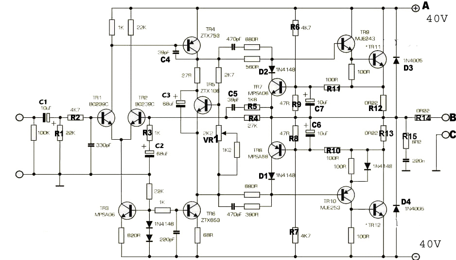
If you compare Les's NCC200 diagram, to the original NAP250 schematic on Acoustica there's an extra 0R22 resistor (marked as R14). I think it's this one that is suggested could be replaced by the 15R & hand wound inductor assembly.

NAP250%20schematic.jpg


Paul
 
Oops yes I stand corrected. For some reason I had it in my head that the intention was to replace one of the other two, which would be a bit silly!

It won't make any difference if it's installed in addition though.
 
Thanks for the input everybody. Based on this, I'll simply put the gizmo in series with the 'speakers.
bry
 
The NAP circuit was based on an RCA design. There's a link to it in post #5 on this thread:

http://www.pinkfishmedia.net/forum/showthread.php?t=68215

There's a 10uH choke in parallel with a 22R resistor in the output of the RCA circuit.

P.S. I've seen early NAP boards (from bolt down 160s) that have the bias transistor thermally attached to the heat sink of one of the driver transistors.

DSCF0192.jpg

Correct Malcolm the original was and RCA design from1972 available from here if you sign up.
https://openlibrary.org/books/OL5339151M/RCA_solid-state_power_circuits_designer's_handbook.

Circuit here from DIY Audio
http://www.diyaudio.com/forums/solid-state/112453-nap-140-clone-amp-kit-ebay-124.html#post4066490

Alan
 
Hitachi did develop the archetypal MOSFET power amp circuit, to sell their new power MOSFETs at the time.

Indeed they did and the circuit was used by many manufacturers
across the world of audio including Musical Fidelity, Bose and Perreaux
to name but a few.
 
What nobody has touched on is if one meter of 4mm mains cable plus the coil+resistor sounds different (better? worse?) than 3.5 meters of NACA5. Has anyone tried and noticed a difference? If not, what is the point of spending £300 and sessions of all-in wrestling to hide the excess behind the speakers?
 
What nobody has touched on is if one meter of 4mm mains cable plus the coil+resistor sounds different (better? worse?) than 3.5 meters of NACA5. Has anyone tried and noticed a difference? If not, what is the point of spending £300 and sessions of all-in wrestling to hide the excess behind the speakers?

Whether it sounds better or worse, I'm not able to pontificate but what I
can say is that the results of relying on extra lengths of cable to ensure
amplifier stability will be variable according to location and the proximity
of RF and HF sources.

Adding the inductor is a known quantity which brings about consistent stability
and the opportunity to choose whatever cables/lengths suits the owner - surely
a desirable outcome - is it not.?

For what it's worth, the NCC200 is difficult (efforts so far have failed), to
provoke into instability.

With the standard NAP board, you pay your money and take your chances.


advertisement


Back
Top