
You are using an out of date browser. It may not display this or other websites correctly.
You should upgrade or use an alternative browser.
You should upgrade or use an alternative browser.
TDL Studio 4
- Thread starter Chops54
- Start date
SubsonicDan
Member
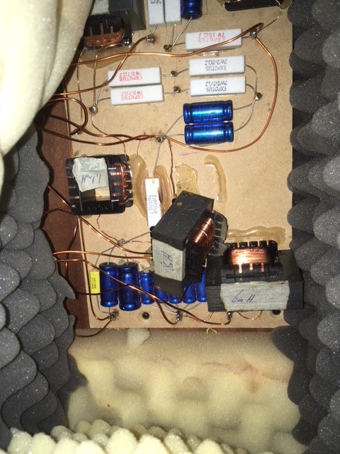
Apologies for resurrecting this ancient thread! But I am also looking for definitive circuit diagrams for TDL Studio 4s (or TDL Monitors) - I recently bought a pair and discovered that the crossovers had been replaced with something very home-made looking, (components soldered point to point to what look like nails on a piece of mdf) The bass drivers are playing roughly 6dB down compared to the mids and highs. As a temporary measure I am bi amping them, allowing me to attenuate the feed to the mid/high, which has been surprisingly successful! But I would be far happier to get hold of a couple of original crossovers, or at least a circuit diagram so I can build my own.
I've googled it to death and only found one source, from a blogger in Italy who was refurbing/modifying a pair - but it is not clear whether the circuit is the original design, or his own concoction. The Blog is very old, most of the links are dead, and there's no obvious way to contact the author.
http://www.cma4ch.org/chemo/image/hifi/TDL-Monitor-Studio4.png
The circuit is completely different in design and the values of the components compared to what is installed in mine. A helpful member on another forum forwarded the circuit diagram from a pair of TDL Monitors (a similar design in many ways, but a 4-way, with super-tweeters) but the circuit layout was completely different again, and unfortunately the values of many of the components was not indicated.
I have contacted Jerry at Falcon. He was as helpful as he could be but only had the same image as in the link from the Italian blog, and was not confident that it was correct either.
I have also contacted Axel at A.O.S. (who used to distribute a variation of the TDL Monitors in kit form) but so far he hasn't been able to find anything for me, although he did confirm that the crossover for the Studio 4 was initially based on the design for the Monitor.
Any help would be much appreciated!
Dan
SubsonicDan
Member
Hi Si, thanks very much - If you have any pics or info in your archives then that would be amazing - as for removing your crossover, that's really above and beyond...
Yes, I've been looking for a good pair of either these or the Monitors for a long time. I was outbid on a promising looking pair a few months ago, I've seen some others, but they needed too much work, bad drivers, tatty cabinets, bits missing - The cabinets and drivers on these are in great shape, but I was quite disappointed when I discovered what was going on inside!
cheers,
Dan
SubsonicDan
Member
Hi David, you make a good point!
I just checked the Elac data sheet again, it says the bass drivers in the Monitor and Studio 4 should be 3021GT 03, DCR 5.2Ω (sensitivity 87.5)
On closer inspection, the 3 bass drivers I have appear to be 3021GT 01, DCR measures 7.4- 7.5Ω, (and according to the data sheet, sensitivity 86) - I say “appear” because only one of the three is actually marked on the chassis, but they all measure around 7.5Ω.
So regardless of whether I continue with the current x-overs, or find the original designs, I’ll either have to find a pair of GT 03 (unlikely), or continue to run them bi amped (or possibly alter the design of the part of the crossover which feeds the mids and highs. Off the top of my head, is it as simple as adding a resistor in series to that part of the circuit to attenuate their output?)
Thanks,
Dan


SubsonicDan
Member
Motors are working, cones & surrounds appear good. The gasket on the backs of the bass drivers could be better and they are probably not making a perfect seal here, also the speaker terminal plate might benefit from a better seal, all on my jobs list - my impression is that the output of the bass drivers is down across their whole range (they crossover at 300hz) rather than just the bass though, so I think that they're basically just the wrong drivers, with too high DCR as you say.Better to find out why the bass is low. Are the motors all working, have you got a detached cone or surround? Air leaks can kill bass
SubsonicDan
Member
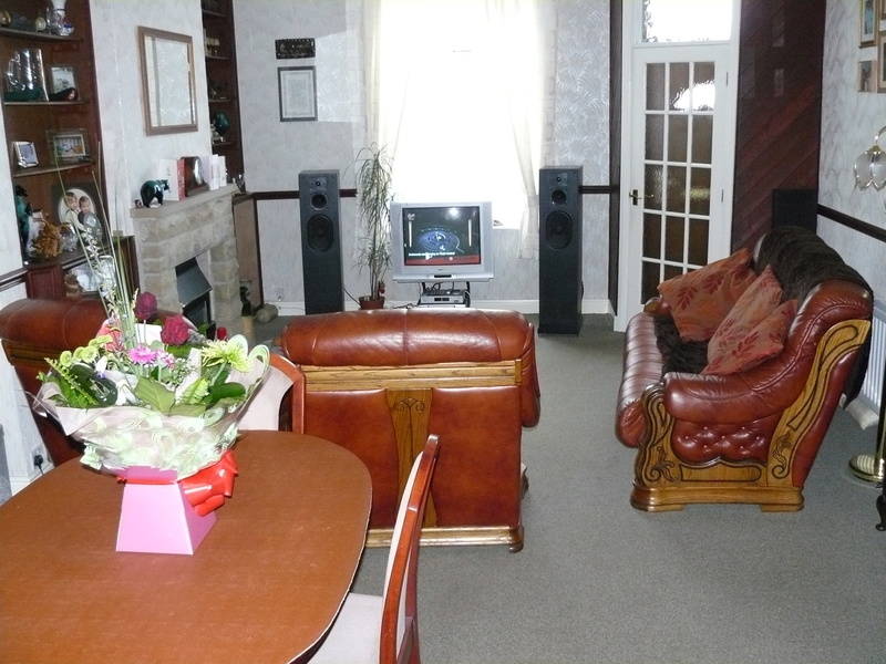
Ok, these are the few pics I have left of my crossovers and the only one I can find of the speakers.
Thanks again Si.
Ha!! I was hoping to find something similar when I opened up mine. But instead I have this...
Last edited:
SubsonicDan
Member
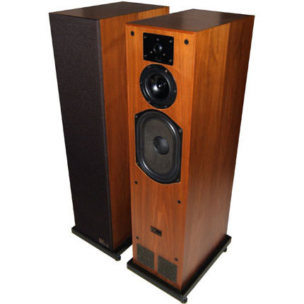
Might be an idea to post a pic of your speakers so we can confirm that they are what you think they are.
I'm not sure what else they could be!
Last edited:
Chops54
pfm Member
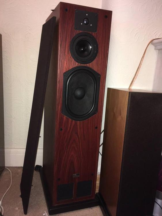
I have to say they are lovely looking speakers, so much more appealing than mine and its good you've got the stands for them. I've never seen a pair of Studio 4s with those mids and tweeters. The only mids I've seen have a four bolt mounting and are rebated into the baffle. Have you removed a mid driver yet?
davidsrsb
pfm Member
Definitely a strong cabinet similarity to the later RTL and T-Line models. I know that TDL was a very small scale operation in Reading, so it is possible that they had QC problems and fitted the wrong drivers.
More likely though, that the obviously home made crossover is messed up and attenuating the bass. An attempt at baffle step compensation would do this.You could safely connect the woofer directly to your amplifier and see if the bass output is much higher
More likely though, that the obviously home made crossover is messed up and attenuating the bass. An attempt at baffle step compensation would do this.You could safely connect the woofer directly to your amplifier and see if the bass output is much higher
SubsonicDan
Member
I have come across images online and on eBay of Studio 4's with veneered baffle and this arrangement of drivers - It's my belief that there was a cosmetic upgrade to the Studio 4 towards the end of the production run - in a similar way to the Reference Standard M version, the mids having the same circular chassis with 6 mounting holes, and the hf drivers were later 25DTs with the black anodised diaphragm and three mounting screws.
They were even advertised side by side when the new model Reference Standard was released.
The "M" stood for metal when applied to the later Studio 1M and 0.75M - but I'm not sure whether this is the case on the Reference Standard M
The mids on mine have no markings on them whatsoever.
Unfortunately mine have obviously had a somewhat chequered history, and I can only speculate as to how they have come to have the crossovers replaced, or apparently the wrong bass drivers.
Last edited:
SubsonicDan
Member
Definitely a strong cabinet similarity to the later RTL and T-Line models. I know that TDL was a very small scale operation in Reading, so it is possible that they had QC problems and fitted the wrong drivers.
More likely though, that the obviously home made crossover is messed up and attenuating the bass. An attempt at baffle step compensation would do this.You could safely connect the woofer directly to your amplifier and see if the bass output is much higher
Thanks again David,
I don't know anything about baffle step compensation other than what I just googled. The crossover circuit for the LF driver is very straightforward though, with a capacitor (or five) in parallel with the driver (no idea of the total value of the cap, the writing on them is just too small for me to read), and an inductor (marked as 6mH) in series. This circuit is adding about 1.3Ω to the DCR across the bass input terminals (8.8Ω compared to 7.5Ω across just the disconnected driver.)
When I get a chance I'll check, as you say, by connecting directly to the amp.
Chops54
pfm Member
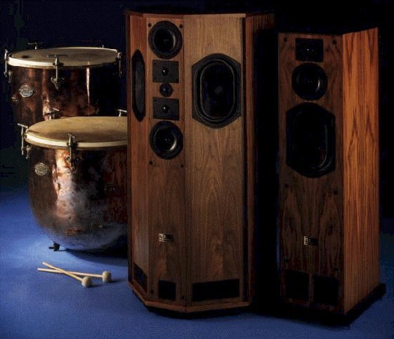
I'm sure I've seen that pic before somewhere. It's the kettle drums that ring a bell. ( Theres a joke in there somewhere") ) I'll try and call in on a friend tomorrow. He has a load of old brochures and stuff for IMF, TDL, B&W etc. Jeez, these speakers must be getting on a bit, thirty or forty years and my memory is past its best I'm afraid.
) I'll try and call in on a friend tomorrow. He has a load of old brochures and stuff for IMF, TDL, B&W etc. Jeez, these speakers must be getting on a bit, thirty or forty years and my memory is past its best I'm afraid.
) I'll try and call in on a friend tomorrow. He has a load of old brochures and stuff for IMF, TDL, B&W etc. Jeez, these speakers must be getting on a bit, thirty or forty years and my memory is past its best I'm afraid.awkwardbydesign
Officially Awesome
Home made? When it has the TDL markings on it?More likely though, that the obviously home made crossover is messed up and attenuating the bass.
JensenHealey
pfm Member
... I tried enlarging the picture and could not see any reference to TDL on it.
Stunsworth
pfm Member
Home made? When it has the TDL markings on it?
The one that has TDL on it - Tranducer Development Limited - isn’t from the OP.